AUF 800 Mechanical Fuel Pump
Description
Design trends and equipment fitted to meet mandatory requirements contribute towards higher underbonnet temperatures. To meet the demand for a mechanical fuel pump capable of handling fuel at high temperatures, SU produced the versatile AUF 800 series. Of sealed unit construction, this type of mechanical pump offers excellent vapour handling capacity and 11 gal/hr pump capacity, the multi-construction inlet and outlets, with optional screwed and push-on connections, simplifying installation.
Special features:
1) Robust zinc die-cast sealed unit construction
2) Ease of installation:
Alternative inlet and outlet nozzle positions
Push-on or screwed connections
Alternative inlet and outlet nozzle sizes
4) Excellent vapour handling capacity
5) Efficient priming
6) Alternative lever or push-rod operation
7) Efficient crankcase seal
8) Competitively priced
The AUF 800 pump is mounted vertically adjacent to an eccentric drive usually on the engine crankcase or camshaft housing. Holes are provided for mounting the pump on two 8.00mm (5/16") studs. Two gaskets with an insulating block between them provide for sealing and heat protection. They also determine the correct position relative to the pump drive and retain the rocker lever pivot pin. The pump is actuated by the rocker lever directly from the engine cam or by an intermediate push-rod.
The pump comprises two main castings; the upper and lower bodies, and two nozzles; inlet and outlet.
Two versions of the pump are available; in one the castings and nozzles are formed into a sealed unit and in the other the nozzles are detachable.
The body (1) consists of an upper and lower die casting between which the diaphragm assembly (2) is clamped. A lip on the lower body is rolled over the upper casting to form an hermetic seal.
The upper casting houses the moulded inlet (3) and outlet (4) valves and bosses are formed in it to accept the inlet (5) and outlet (6) nozzles. The lower casting contains the rocker lever (7), pivot pin (8), rocker lever tension spring (9), diaphragm spring (10) and the crankcase seal located beneath a pressed steel cup (11).
The inlet (5) and outlet (6) valves are identical mushroom-shaped elastomeric mouldings controlling ports formed in the upper body casting.
The riveted diaphragm assembly consists of a single reinforced diaphragm with two large diameter backing plates and a stirrup.
A small spring (9), acting on the rocker lever, keeps it in contact with the engine cam or push rod at all times. The diaphragm spring (10) controls the fuel delivery pressure.
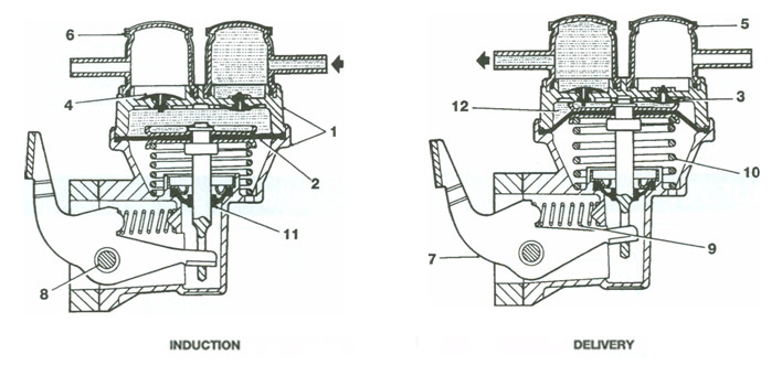
Action Induction
When the diaphragm (2) is pulled down by the rocker lever (7), fuel is drawn into the inlet nozzle (5), passing downwards past the lip of the moulded inlet valve (3) into the diaphragm chamber (12).
Delivery
When pressure on the rocker lever is released the diaphragm (2) moves upwards under the influence of the diaphragm spring (10). The pressure in the diaphragm chamber ensures that the inlet valve is firmly closed and fuel is discharged past the lip of the moulded outlet valve (4) into the outlet nozzle (6).