Basic Principles of the SU Carburetter
The majority of car engines rely on carburetters to provide them with the finely atomized fuel/air mixture necessary for satisfactory performance. The carburetter must provide good atomization and the correct mixture strength under all operating conditions of the engine. The method used to do this in all carburetters is to speed up the velocity of the air by means of a venturi or choke and to use the consequent reduction of pressure in the venturi to draw fuel from the float chamber through a suitable jet orifice into the air stream.
The ideal carburetter is an instrument which when correctly tuned will supply its engine with the optimum mixture for maximum power throughout the full throttle range and for minimum consumption under all part-throttle conditions.
The Fixed Choke
When air is passed through a choke of fixed size its velocity and the depression over the fuel jet will vary with the demands of the engine. This varying depression makes it necessary to employ compensating devices to produce the correct fuel flow and also imposes a compromise on the choice of choke size in that too small an orifice will produce a restriction, at the top end of the output range whilst a large orifice will cause poor metering and indifferent carburetion at the lower end of the range.
The Variable Choke
The principle of the variable choke carburetter is to employ a means whereby the effective choke orifice will expand as the demand increases, and contract when the demand diminishes. Such a variation in choke area will achieve a constant air velocity and depression over the jet.
Basic Construction
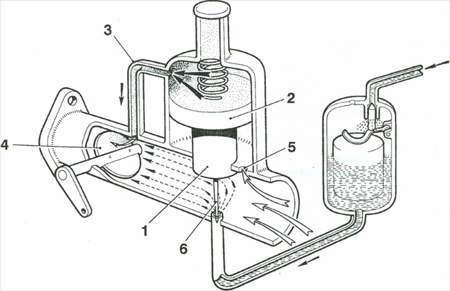
A variable choke orifice is obtained in the SU carburetter by the vertical movement of a close-fitting piston (1) positioned above the fuel jet in the centre of the body casting. A suction disc (2) is integral with the piston and works in a concentric chamber bolted to the top of the body casting.
Drillings in the under face or side of the piston, shown for simplicity as an external duct (3) communicate any depression existing in the space between the piston (1) and the throttle disc (4) to the chamber above the suction disc (2). The underside of the suction disc is vented to atmosphere or to the air cleaner by transfer holes located in the inlet flange, shown simply by the drilling (5).
As the choke orifice is varied over wide limits by the movement of the piston throughout the speed range, the fuel jet orifice must also be varied. This is achieved by means of a tapered needle (6) attached to the piston and projecting into the jet. Correct discharge areas are obtained by the accurate dimensioning of this needle.
Opening the throttle disc (4) allows the manifold depression to be communicated to the body of the carburetter and also to the chamber above the suction disc. The piston will rise, allowing a mixture of air and fuel to pass underneath it to relieve the depression. The piston will continue to rise until the depression has reached a value which is just sufficient to balance the weight of the piston, together with the load exerted by the piston spring.
It will be appreciated that approximately the same depression can be obtained whatever the demand and that the piston height will be governed by the mass of mixture flowing beneath it. This depression is arranged to be of sufficient value to ensure that good atomization is obtained, but small enough to ensure adequate engine filling at high speeds.
Additions to the Basic Design
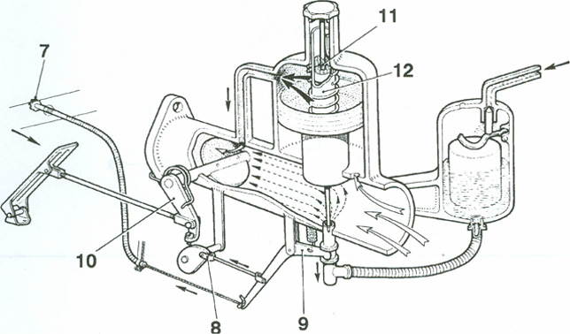
Operation of the cold start mixture control (7) will lower the jet down the needle (maximum movement 7/16" or 11 mm) exposing a large annulus and so providing the rich mixtures required for the cold start and initial 'warm up' period.
On later integral float (HIF) carburetters, the cold start enrichment is provided by means of a separate fuel path between the float chamber and the constant depression region close to the jet orifice. The fuel flow through this path is controlled by a rotary valve.
On most SU carburetters there is a connection (8) between the jet lever (9) and the throttle disc control (10). The connection is such that on operation of the cold start/misture control, the first few degrees of movement of the jet lever (9) open the throttle disc without moving the jet. Successive movement of the jet lever lowers the jet and opens the throttle disc by a further amount, providing enrichment.
A one-way valve is incorporated in the damper plunger (11) and this is fitted in an oil-fitted reservoir in the hollow piston rod (12). The piston damper assembly will restrict the rate by which the piston lifts, but will allow it to fall freely on throttle closure. The primary purpose of the piston damper is to provide the enrichment necessary for a satisfactory 'pick-up' during rapid opening of the throttle.
This enrichment is achieved by the damper retarding the speed of piston lift, thereby creating an additional depression over the jet which increases the amount of fuel discharged. When the engine is cold, the viscosity of the oil in the damper is high and the enrichment obtained is therefore greater than when the oil is warm.
Practical Application
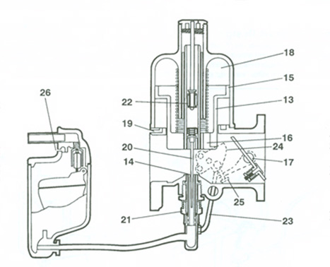
The diagram shows a sectional representation of a type HS carburetter, float chamber moved out of position, which shows how the operation of the SU carburetter is achieved in practice.
The depression is communicated to the suction chamber (18) by means of the depression transfer drillings (16) in the bottom of the close-fitting piston (13).
Cold start enrichment is provided by clockwise rotation of the fast-idle cam (24). This is usually effected by a Bowden-type flexible cable which is operated from a position convenient to the driver. Initial rotation of the cam takes up lost motion built into the jet drop link and brings the cam into contact with the fast-idle screw (25). This causes the throttle to start opening. Further rotation of the cam increases the throttle opening still further and also pushes the link (23) which lowers the jet, thus providing enrichment.
The diagram also details the fuel jet (14), suction disc (15), throttle disc (17), atmospheric vent passage (19), jet needle (20), mixture adjusting nut (21), hydraulic damper (22) and float chamber vent (26).
The basic means of adjusting the carburetter are:
- Jet adjustment for mixture strength
- Slow run screw adjustment (not shown) for engine idling speed
- Fast-idle speed adjustment by means of fast-idle screw (25).