Single Type Electric Fuel Pumps
The pump comprises three main assemblies: the body casting, the diaphragm, armature and magnet assembly, and the contact breaker assembly.
The Body
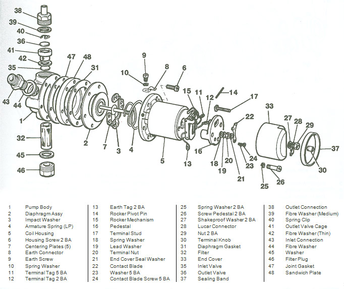
L and HP Type Pumps
The body (1) consists of a casting and a sandwich plate (48) which is assembled to it together with a joint gasket (47). A filter (32) is screwed into the lower part of the body, and the inlet union (43) is screwed in at an angle on one side. The outlet union (38) is screwed into the top of the body, opposite to the filter, and tightens down onto the delivery valve cage (41), which is clamped between two fibre washers, thin (42) and medium (39). In the top of the cage is the outlet valve, a thin brass disc (36) held in position by a spring clip (40). The inlet valve (35), a similar brass disc, rests on a seating machined in the body. A series of holes connects the space between the valves to the pumping chamber which is a shallow depression on the face of the sandwich plate, bounded by the diaphragm assembly.
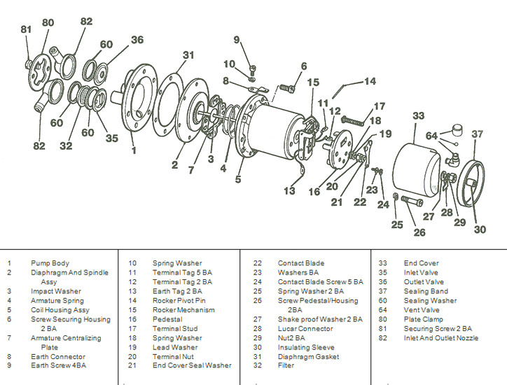
AUF 200/AZX 1200
The body (1) is a casting into which the clamp plate (80), retained by two screws (81), holds the inlet and outlet moulded nozzles (82) and both valve assemblies, all of which are arranged to be accessible from the outside of the pump. The inlet valve (35) consists of a thin plastic disc permanently assembled into a pressed steel cage. The outlet valve (36) is an identical assembly, but reversed in direction. A dome-shaped filter (32) is provided on the entry side of the inlet valve. The valve allows passage to the pumping chamber - a shallow depression formed in the face of the body casting and bounded by the diaphragm.
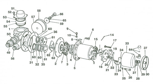
AUF 300/AZX 1300
The main fuel inlet (56) is in communication with an inlet air bottle (flow-smoother), and connection to the main pumping chamber is provided by the inlet valve assembly (65). This comprises a plastic valve disc permanently assembled within a pressed-steel cage, which is held in place by a valve cover (61). The outlet from the pumping chamber is provided with an identical valve assembly (36) reversed in direction. A clamp plate (62) secured by self-tapping screws (63) holds both inlet and outlet valve assemblies in position: the valves may be removed by releasing the clamp plate screws. A filter (32) is provided as shown - on the entry side of the inlet valve assembly.
The outlet flow-smoothing device is fitted across the extremity of the delivery chamber which communicates with the outlet union (49). The outlet smoothing device assembly consists of a flexible plastic diaphragm (54) contained between the domed cover and the outlet chamber.
The inlet valve (65) allows passage to the pumping chamber which is formed by a shallow depression in the body casting and bounded by the diaphragm (2).
The Diaphragm, Armature and Magnet Assembly
The diaphragm (2) is clamped at its outer edge between the coil housing (5) and the body, and attached at its centre to the iron armature. The armature spindle passes freely through the magnet core, and is screwed into a trunnion carried by the inner rocker (15). A plastic armature guide plate (7) centralises the armature and allows freedom of movement in a longitudinal direction. An atmospheric vent may be fitted to the coil housing.
The Contact Breaker Assembly
This assembly consists of a bakelite pedestal moulding (16) which carries two rockers, outer and inner (15), both hinged to the moulding at one end by the rocker spindle and interconnected at their top ends by two small toggle springs arranged to give a 'throw over' action. The inner rocker, as mentioned, carries a trunnion into which the armature spindle is screwed. The outer rocker is fitted with one or two tungsten points which contact other tungsten points carried by the spring blade (22).
One end of the coil (5) is connected electrically to the spring blade and the other end is connected to the terminal stud (17). A short length of flexible wire (13) connects the outer rocker to one of the screws securing the pedestal moulding to the coil housing, thus providing an earth return. This wire must then be thoroughly earthed to the body or chassis of the vehicle via the earthing screw (9). A non-return valve (64) may be fitted to the end-cover moulding (33) to aid the circulation of air through the contact-breaker chamber. A diode-resistor (34), where fitted, is in parallel with the points as a spark suppressor to increase the life of the points. Some earlier models were fitted with a condenser rather than a diode resistor.
Operation
When the pump is at rest, the outer rocker lies so that the tungsten points make contact. When switched on, current passes from the terminal stud (17) through the coil, back to the spring blade (22), through the points and so to earth, thus energizing the coil and attracting the armature (2). The armature, together with the diaphragm assembly, moves towards the coil, against pressure from the armature spring (4), drawing fuel through the inlet valve into the pumping chamber. When the armature has travelled well towards the end of its stroke the 'throw over' mechanism operates and the outer rocker moves rapidly backwards, thus separating the contact points and breaking the circuit.
The armature and diaphragm will now move away from the coil under the influence of the armature spring, thereby expelling the fuel through the outlet valve at a rate determined by the requirements of the engine. As the armature approaches the end of its stroke, away from the coil, the 'throw over' mechanism again operates, the tungsten points re-make contact, and the cycle of operations is repeated.
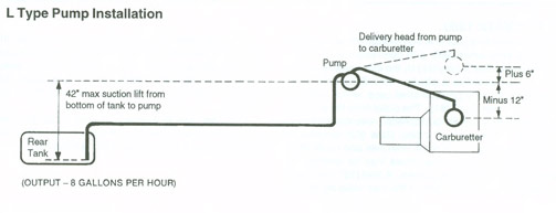
Installation
Where pumps with vents are used, the vent should be piped to a region of dry air, for example the car interior or luggage compartment. The following diagrams give typical installation configurations.
HP Type Pump Installation
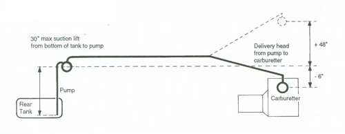
The type HP pump, because of its high delivery pressure, is very suitable for mounting over the rear fuel tank, in which position it is also free from vaporising troubles arising from high under-bonnet temperatures.
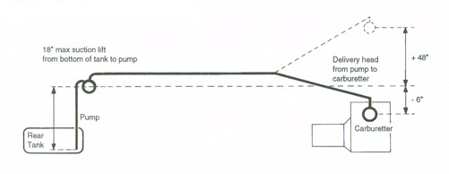
AUF 200/AZX 1200 Pump Installation
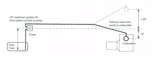
AUF 300/AZX 1300 Pump Installation
Performance
| Type | Voltage | Minimum Voltage* | Current at Minimum Voltage |
| L HP AUF 200/AZX 1200 AUF 300/AZX 1300 |
12 12 13.5 13.5 |
9.5 9.5 |
1.5A 1.5A |
| Type | Capacity | Bore of Pipe | Maximum Line Pressure |
| L HP AUF 200/AZX 1200 AUF 300/AZX 1300 |
8 gal/hr 7 gal/hr 7 gal/hr 15 gal/hr |
0.25" 0.25" 0.25" 0.312" |
1.5 Ib/in2 2-3.8 Ib/in2 2.7lb/in2 2.7/3.8 Ib/in2 |
*9.5V is the minimum starting voltage for pumps with standard coils. Some pump specifications use alternative coils which offer reduced minimum starting voltage.