HIF Type Carburetter: Reassembly
Reassembly by reversing the procedure used to dismantle the carburetter, noting the following:
- Ensure that the throttle disc is fitted in its original position.
- New throttle disc retaining screws must be used when refitting the disc. Ensure that the throttle disc is correctly positioned and closes correctly before tightening the retaining screws. Spread the split ends of the screws sufficiently to prevent turning.
- Position the throttle spindle end seals just below the spindle housing flange.
- The starter unit valve is fitted with the cut-out towards the top retaining screw hole and its retaining plate is positioned with the slotted flange towards the throttle spindle. Apply a smear of oil to the starter 'O' ring prior to assembly, the starter should then enter the carburetter body with ease. If force has to be used this will invariably result in damage to the 'O' ring.
- When fitting the jet assembly to the adjusting lever ensure that the jet head moves freely in the bi-metal cut-out.
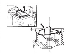
- After fitting the float and valve, invert the carburetter so that the needle valve is held in the shut position by the weight of the float only. Check that the point indicated on the float (see illustration) is 1.0 +/- 0.5 mm (0.04 +/- 0.02 in) below the level of the float chamber face (see illustration). Then adjust the float position by carefully bending the brass pad. Check that the float pivots correctly about the spindle.
- Ensure that the needle guide fitted gives the needle bias in the required sense (either toward throttle disc or toward air cleaner). Before tightening the retaining screw, check that the needle guide is in its correct position relative to the piston face, either flush with the bottom of the piston on standard pistons or flush with the recess on recessed pistons.
- Ball bearing suction chambers. To prevent piston spring from being "wound up" during reassembly, temporarily fit the piston and suction chamber, less the piston spring, to the body and pencil mark their relative positions to each other. Fit the spring to the piston, hold the suction chamber above the piston, align the pencil marks and lower the chamber over the spring and piston. It is essential that the bearing retention clip (early type) or the bearing retention circlip (later type) is correctly fitted.