AUF 700 Mechanical Fuel Pump
Description
The AUF 700 pump is mounted on the crankcase on two 5/16" UNF studs with a heat insulating block and two gaskets, the total thickness of which should not be altered.
The pump lever (1) abuts against the engine cam or push-rod in the space between the camshaft and the side of the crankcase. The rocker lever pivot pin (2) is retained by the walls of the insulating block.
The outlet cover (3) and its sealing washer (4) are secured by three long No. 10 UNF screws (5).
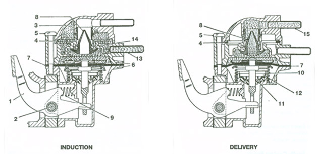
The body (6) consists of an upper and lower diecasting, between which the diaphragm assembly (7) is clamped. Three short No. 10 UNF screws secure the two halves of the body together, the upper casting containing the inlet and outlet valve moulding (8) and the lower casting containing the rocker lever (1), pivot pin (2), rocker lever tension spring (9), diaphragm spring (10) and the crankcase seal (11) beneath a pressed steel cup (12).
The larger diameter of the combined valve moulding (8) forms the inlet valve and the two lips at the peak of the moulding form the outlet valve. The valve is a press-fit into its housing on the under-side of the upper body.
The diaphragm assembly (7) is riveted and therefore cannot be separated in service. It comprises three separate layers attached to a stirrup which is operated by the rocker lever.
Two springs are fitted, the smaller one (9) keeping the rocker lever in contact with the engine cam at all times, the larger spring (10) controlling the fuel delivery pressure.
Action Induction
When the rocker lever is actuated by the engine cam, the diaphragm assembly moves downwards and fuel is drawn through the inlet nozzle (13) into the upper body. The fuel passes upwards through the filter (4) into the outer cover, and then flows downwards through an annular passage (14) formed outside the valve housing, past the lip of the large diameter inlet valve flap into the diaphragm chamber.
Delivery
When the engine cam lobe passes the rocker lever pad, the diaphragm (7) is allowed to move upwards under the influence of the diaphragm spring. The pressure generated in the diaphragm chamber ensures that the inlet valve flap is firmly closed and fuel is discharged through the outlet valve lips into the centre of the outlet cover and thus to the nozzle (15).