Electric Fuel Pump: Reassembly
L and HP Types
1
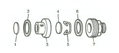
(a) Assemble the brass valve disc (4) to the outlet valve cage (3), making sure that the smooth face of the disc faces the valve seat.
(b) Retain the disc in position with the circlip (5) which must be located in the groove in the valve cage. The valve must rattle freely when the valve cage is shaken.
(c) Drop the other valve disc (1) smooth face downwards onto the inlet valve seat in the body of the pump.
(d) Inset the thin fibre washer (2), drop the valve cage (3) in position, insert the medium fibre washer (6) then screw in the outlet union (7) and tighten with a 3/8 inch Whitworth ring or box spanner.
(e) Fit the outlet union.
2
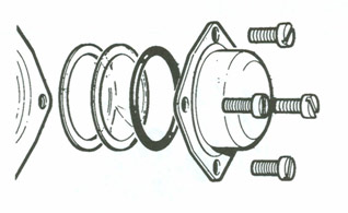
(a) Place the sandwich plate gasket onto the face of the body, lining up the holes in the body and gasket. Fit the sandwich plate, concave face to diaphragm together with the diaphragm gasket, again lining up the holes.
(b) Offer up the coil housing to the body and sandwich plate and ensure correct seating between them. Outlet connection to the top and filter plug at the bottom.
(c) Line up the six securing screw holes, making sure that the two cast lugs on the coil housing are at the bottom. Inset the six 2 BA screws finger-tight. Fit the earthing screw with its Lucar connector.
(d) Tighten the securing screws in sequence as they appear diametrically opposite each other.
All Other Types
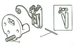
Note: The steel pin which secures the rocker mechanism to the pedestal is specially hardened and must not be replaced by other than a genuine SU part.
1
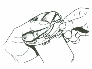
(a) Invert the pedestal and fit the rocker assembly to it by pushing the steel pin (1) through the small holes in the rockers and pedestal struts.
(b) Then position the centre toggle so that, with the inner rocker spindle in tension against. the rear of the contact point, the centre toggle spring is above the outer rocker spindle (as in insert).
(c) This positioning is important to obtain the correct 'throw-over' action; it is also essential that the rockers are perfectly free to swing on the pivot pin and that the arms are not binding on the legs of the pedestal.
(d) If necessary the rockers can be squared up with a pair of thin-nosed pliers.
(e) Assemble the square-headed 2 BA terminal stud (2) to the pedestal, the back of which is recessed to take the square head.
2
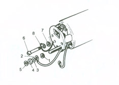
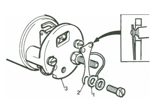
(a) Assemble the 2 BA spring washer (1) and put the terminal stud through 2 BA terminal tag (2), then fit the lead washer (3) and the coned nut with its coned face to the lead washer. (This makes better contact than an ordinary flat washer and nut.)
(b) Tighten the 2 BA nut and finally add the end-cover seal washer (5).
(c) Assemble the pedestal to the coil housing (see figure 2) by fitting the two 2 BA pedestal screws (6), and ensure that the spring washer (7) on the left-hand screw (9 o'clock position) is between the pedestal and the earthing tag (8).
(d) Tighten the screws, taking care to prevent the earthing tag (8) from turning, as this will strain or break the earthing flex. Do not over tighten the screws or the pedestal will crack.
(e) Do not fit the contact blade at this stage
3
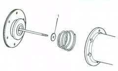
(a) Place the armature spring into the coil housing with its large diameter towards the coil.
(b) Before fitting the diaphragm, make sure that the impact washer (1) is fitted to the armature. (This is a small neoprene washer that fits in the coil recess.) Do not use jointing compound or dope on the diaphragm.
(c) Fit the diaphragm by inserting the spindle into the hole in the coil and screwing it into the threaded trunnion in the centre of the rocker assembly.
(d) Screw in the diaphragm until the rocker will not 'throw over'; this must not be confused with jamming the armature on the coil housing integral steps.
(e) On later-type rocker mechanisms with adjustable fingers, fit the contact blade and adjust the finger settings, then carefully remove the contact blade.
4
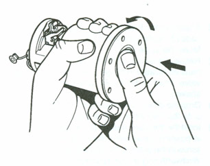
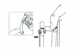
(a) Holding the coil housing assembly in the left hand in an approximately horizontal position, push the diaphragm spindle in with the thumb of the right hand, pushing firmly but steadily.
(b) Unscrew the diaphragm, pressing and releasing with the thumb of the right hand until the rocker just 'throws over'.
(c) Now turn the diaphragm back (unscrew) to the nearest hole and again a further four holes (two-thirds of a complete turn). The diaphragm is now correctly set.
5
Fit the eleven brass armature guides by turning back the diaphragm and placing them into the recess between the diaphragm and the armature plate. Make sure these do not fall between the armature plate and coil housing assembly.
6
AUF 200/AZX 1200 Type Only
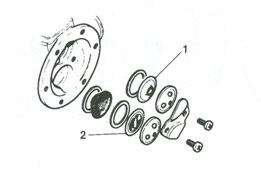
In this range of pumps, the inlet (2) and outlet (1) valves are identical assemblies and are held in position in the one piece body casting by a steel spring clamp plate secured by two 2 BA screws. This plate also secures the inlet and outlet nozzles, including the filter, all of which are arranged to be accessible from the outside of the pump. The inlet recess is deeper than the outlet to allow for the filter and extra washer.
(a) Place the outlet valve assembly (tongue-side uppermost) in the recess marked 'outlet'. Place a joint washer on top of the valve assembly and complete this part of the assembly by adding the outlet nozzle.
(b) Place the inlet valve assembly (tongue-side downwards) in the recess marked 'inlet'. Follow this with a joint washer, then the filter (dome side upwards), then another joint washer, completing the assembly with the inlet nozzle.
(c) Take care that both assemblies settle down evenly into their respective recesses. Position the nozzles as required, place the clamp plate on top, and tighten down firmly onto the body with the two 2 BA screws.
AUF 300/AZX 1300 and Dual Types Only
In this range of pumps the valve assemblies are retained internally in the body by a clamp plate secured with self-tapping screws. The inlet valve (2) recess in the body is deeper than the outlet (1) recess to allow for the filter and the extra washer.
Another feature of these pumps is the incorporation of an air bottle on the inlet and a flow-smoothing device on the delivery side.
The inlet air bottle is a chamber in the body casting blanked off by a simple cover and joint washer held in place by a single screw.
The delivery air bottle is formed by a flexible plastic diaphragm, separating the delivery chamber in the body from a sealed volume of air contained in the air bottle cover. This cover is secured by four screws and sealed by an O section sealing ring and joint washer.
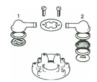
(a) Screw in the inlet and outlet connections together with their sealing rings. Assemble the outlet valve components into the outlet recess in the following order: first a joint washer, and then the valve (tongue-side downwards), then the valve cap.
(b) Assemble the inlet valve into the inlet recess as follows: first a joint washer, then the filter (dome side downwards), then another joint washer, followed by the valve assembly (tongue-side upwards), then the valve cap. Take care that both valve assemblies settle down into their respective recesses. Place the clamp plate on top and tighten down firmly to the bottom with the two (four in dual types) screws.
(c) Replace the inlet air bottle cover with its joint washer and tighten down the central screw.
(d) Place a sealing washer in the bottom of the delivery air bottle recess. Place the plastic diaphragm (dome side downwards) then add the 0 section sealing ring and tighten down the cap with its four screws.
(e) The pump should be pressure-tested after disturbance of the delivery air bottle.
7
All types
(a) Fit the joint washer to the body, aligning the screw holes. Offer up the coil housing to the body, ensuring correct seating between them.
(b) Line up the six securing screw holes, making sure that the cast lugs on the coil housing are at the bottom. Insert the six 2 BA screws finger-tight.
(c) Fit the earthing screw with its Lucar connector.
(d) Tighten the securing screws in sequence as they appear diametrically opposite each other.
(e) Dual Types: Repeat these operations on the other coil housing.
8
(a) Fit the contact blade (2) and coil lead (1) to the pedestal (3) with the 5 BA washer and screw. Where a diode resistor is fitted it is in parallel with the coil connections. This component is polarity conscious and therefore all connections must be correctly made. A condenser, where fitted, is not polarity conscious.
(b) Adjust the contact blade so that the contact points on it are a little above the contact points on the rocker when the points are closed, also that when the contact points make or break, one pair of points wipes over the centre line of the other in a symmetrical manner. As the contact blade is provided with a slot for the attachment screw, some degree of adjustment is possible.
(c) Tighten the contact blade attachment screw when the correct setting is obtained.
9
(a) Check that when outer rocker is pressed onto the coil housing, the contact blade rests on the narrow rib or ridge which projects slightly above the main face of the pedestal. If it does not, slacken the contact blade attachment screw, swing the blade clear of the pedestal, and bend it downwards a sufficient amount so that when repositioned it rests against the rib lightly. Over-tensioning of the blade will restrict the travel of the rocker mechanism.
10
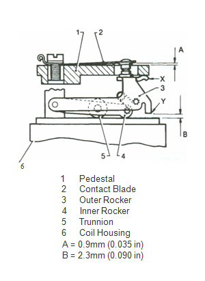
(a) Check the lift of the contact blade tip above the top of the pedestal (A) with a feeler gauge, bending the stop finger 'X' beneath the pedestal, if necessary, to obtain a lift of 0.9mm +/- 0.13 mm (0.035 +/- 0.005 in).
(b) Check the gap between rocker finger and coil housing (B) with a feeler gauge bending the stop-finger 'Y', if necessary, to obtain a gap of 2.3 mm +/- 0.13mm (0.090 +/- 0.005 inch).
11
(a) Tuck all spare cable into position so that it cannot foul the rocker mechanism. See that the diode resister or condenser is fitted snugly into the end cover at the correct attitude. Ensure that the end-cover seal washer is in position on the terminal stud.
(b) Fit the bakelite end-cover and lock washer, secure with the brass nut, fit the terminal tag or connector, and then the insulated sleeve.
(c) The pump is now ready for test.
(d) After test replace the rubber sealing band over the end cover gap and seal with adhesive tape. This may be removed to improve ventilation when the pump is mounted internally in a moisture-free region but must be retained otherwise.