THE HD OR DIAPHRAGM-JET-TYPE CARBURETTER AND THE AUXILIARY ENRIGHCHMENT CARBURETTER (THERMO-CARBURETTER)
THE HD OR DIAPHRAGM-JET-TYPE CARBURETTER
The HD carburetter differs from the more familiar type in that the jet glands are replaced by a flexible diaphragm, and the idling mixture is conducted along a passage-way, in which is located a metering screw, instead of being controlled by the throttle disc; the throttle/jet interconnection mechanism is also redesigned.
There alterations give more consistent idling, greater reliability of metering, and reduced choke control load. This carburetter is made in three sizes, 1.5 inch (38.1mm), 1.75 inch (44.4 mm) and 2 inch (50.8 mm), and can have either the manual mixture enrichment already described, or the auxiliary cold starting attachment referred to in the second part of this sheet.
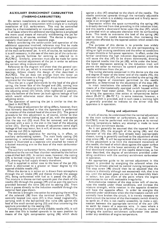
The details of these alterations are as follows (diagram below). The Jet (1), which is fed through its lower end, is attached to a synthetic rubber diaphragm (2) by means of the jet cup (3) and jet return spring cup (4), the centre of the diaphragm being compressed between these two parts; at its outer edge it is held between the diaphragm casing (5) and the float chamber arm. The jet actuating lever (7), the latter having an adjusting screen (8), which limits the upward travel of the jet and thus constitutes the idling adjustment; screwing it in (clockwise) enriches the mixture, and unscrewing it weakens the mixture.
Throttle lever and jet interconnection
The jet and throttle interconnection mechanism is operated by a cam (9), mounted on the jet lever spindle (10), the whole unit being housed in the diaphragm casing (5). The cam on being rotated by means of the jet hand control lever (11) actuates the cam shoe (12), thereby causing vertical movement of the push-rod (13). To the top of this push-rod is attached the top plate (14), which is fitted with an adjusting screw (15) which makes contact with the throttle stop lever (16).
It will be seen that angular movement of the jet hand control lever will turn the jet lever spindle and, therefore, the jet actuating lever which controls the jet cup and the jet. The cam controls the cam shoe, push rod, top plate and the throttle. Suitable setting of the two adjustment screws (8) and (15) will clearly give any desired combination of mixture enrichment and throttle opening.
Vacuum-controlled ignition and economizer ports
The connection to the vacuum ignition control and to the float chamber vacuum-type economizer is made at the top of the carburetter instead of underneath or at the side, as with the older type. This means that the throttle is opened downwards, assuming the throttle lever to be in the normal position, facing the air intake.
Throttle spindle glands
Provision is made for the use of throttle spindle glands consisting of the cork gland itself (22), a dished retaining washer (23), a spring (24) and a shroud (25). This assembly should not require servicing and can only be removed by dismounting the throttle spindle and disc.
Idling
The HD carburetter still idles on the man jet, but the mixture, instead of passing under the throttle disc, is conducted along the passage-way (17) connecting the choke space to the other side of the throttle disc.
The quantity of mixture passing through the passage-way and, therefore, the idling speed of the engine are controlled by the ’slow-run’ valve (18), the quality or relative richness of the mixture being determined by the jet adjusting screw, as mentioned in paragraph 2 under “throttle lever and jet interconnection”. It follows that when idling, once the engine has reached its running temperature, the throttle remains completely closed against the bore of the carburetter; for fast idle, when the engine is cold, it continues to be partially open as with the current design, mixture passing under the throttle disc as well as along the passage-way.
Centering the Jet
This is carried out in much the same way as on the standard H type carburetter, except that the float chamber and jet casing must be removed and the jet held in the uppermost position by hand. It is important to keep the diaphragm and, therefore, the jet in the same radial position in relation to the carburetter body and jet casing, throughout this operation, as the jet orifice is not necessarily concentric with its outside diameter, and turning might cause decentralization. The simplest way to do this is to mark one of the diaphragm and corresponding jet casing screw holes with a soft pencil.
Adjustment
The adjustment of the HD carburetter is extremely simple. Whereas with the older type the jet was controlled by a nut, it is now set by a screw, and whereas the engine speed was determined by adjustment of the throttle, it is now controlled by the ‘slow-run’ valve (18). To enrich the mixture, the screw (8) should be screwed in, and to increase the idling speed the ‘slow-run’ valve should be undone.
Defects in operation
Since the jet of the HD carburetter is fed through its center and has no glands, leakage can only be caused by an insecure fit of the jet cup, an imperfect seal of the diaphragm, either at its outer edge, where it is compressed between the float chamber and the diaphragm casing, or at its inner edge, where it is fitted to the jet, or by a fracture of the diaphragm. Leakage at the outer edge may be cured by tightening the float chamber securing screws (19), but fracture or leaking at the inner edge will probably call for a new jet assembly.
The jet may also stick, up or down, due to dirt between it and its bearing (20), or due to corrosion. The cure is to remove the parts by undoing the jet screw (21), clean and refit.