The SU Carburetter Company
In 1905 Mr. George H. Skinner took out a patent for a carburetter in which both the air and fuel passages varied in accordance with the requirements of the engine. The original design was a clean and simple layout in marked contrast to the multi-jet fixed choke carburetters and it provided a standard of flexibility and economy of operation hitherto unknown.
George Skinner together with brothers John and Carl formed the S.U. Carburetter Company in 1910, setting up business in a small workshop in London. The initials S.U. stand for Skinners Union.
From these beginnings the S.U. Company grew into one of the major manufacturers of car fuel systems and components in Europe, its carburetters being widely used on both touring and competition vehicles.
S.U. carburetters are to be found on such widely differing types of vehicles as the British Leyland Mini and the Rolls-Royce Silver Shadow.
The scope of the Company was later widened by the introduction of its well-known range of electric fuel pumps. More recently the mechanical fuel pump and the sophisticated Automatic Enrichment Device (A.E.D.) have been added.
Today the Company produces over two and a half million carburetters and pumps each year and has embarked on further expansion of its manufacturing and development facilities in order to maintain the unique reputation that S.U. has acquired in the field of carburation equipment and fuel delivery pumps.
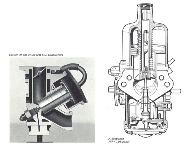
Engine Emission Control
The following features embodied in S.U. carburetters considerably reduce the harmful elements found in engine exhaust gases, and development resources at S.U. are concentrating on producing other improvements which will further assist in solving the pollution problem:
- Spring-loaded jet needle
- Overrun limiting valve
- Integral crankcase
- Ventilation control
- Temperature compensation
- Ball bearing suction chamber assembly.
Spring Loaded Jet Needle
The jet needle is retained in a predetermined position in the jet orifice by means of a spring loaded fixing. This ensures that the same shape and position of the orifice in carburetters of the same specification is maintained with subsequent repeatable emission values.
Overrun Limiting Valve
A precisely set spring-loaded plate valve is located in the throttle disc. The valve opens under high manifold depression conditions, i.e. overrun at closed throttle, reducing the depression and supplying a quantity of correct fuel/air mixture through the throttle disc. The correct combustion achieved reduces the value of hydrocarbon emission which would otherwise be emitted under these conditions.
Integral Crankcase Ventilation Control
Engine fumes and blow-by gases are drawn from the crankcase via a breather hose into the constant depression area between the carburetter piston and throttle disc, eliminating the need for a separate control.
Temperature Compensation (HS4 and HS8 models only)
Bi-metal discs, interposed between the jet and the mixture setting lever, move the jet to compensate for changes in mixture strength which occur with variations in temperature.
Ball Bearing Suction Chamber Assembly*
This is the latest and one of the most important developments to be offered in the specification of a constant depression carburetter. The piston guide rod moves in a double row of ball bearings, thereby virtually eliminating the effects of friction and hysteresis. With this feature stability of carbon monoxide emission at idle speeds is achieved, together with further reduction of emission levels during acceleration and deceleration and improvement in repeatability of emission values.
* This assembly, the subject of a recent S.U. patent application, is available for 38.1 mm (1.5 in), 44-45 mm (1.75 in), and 50-80 mm (2.0 in) carburetters.
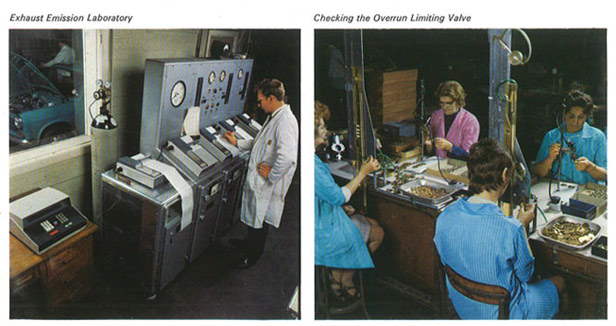
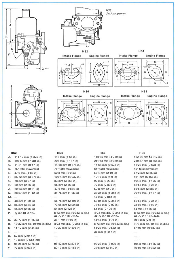
HS Carburetters
The competitively priced HS type (Horizontal Short body) is the latest of a long line of side mounted float-chamber S.U. carburetters. The jet is fed by a flexible nylon tube from the base of the float-chamber and vertical movement of the jet provides cold start enrichment.
The HS type is available for both single and multi carburetter applications complete with all necessary connecting linkage in throttle bore sizes ranging from 31.75 mm (1½ in) to 50.8 mm (2.0 in). They may be mounted at angles ranging from horizontal to 30° downdraught and are available with solid or flexible float-chamber mountings.
Features developed for the control of exhaust emissions described on the previous page can, except where specified, be embodied in the full HS range.
HS Features
- Proved constant depression principle
- R.H. or L.H. float-chamber mounting
- Flexible or solid-mounted float-chamber
- Three controls:
• mixture adjustment
• slow run
• fast idle
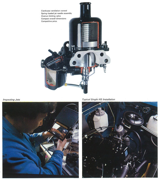
HIF Carburetters
HIF Features
- Proved constant depression principle
- Integral float-chamber
- Float concentric to jet
- Fuel viscosity compensator
- Part throttle by-pass emulsion system
- Rotary valve cold-start enrichment device
- Three controls:
• mixture adjustment
• slow run
• fast idle
- Overrun limiting valve
- Easy accessible mixture adjustment with sealing facility
- Spring-loaded jet needle assembly
- Crankcase ventilation control
- Alternative float-chamber vent positions
- DU throttle bushes and rubber seals
- Competitive price.
To compensate for fuel viscosity variations when the fuel temperature changes, a bi-metal lever immersed in the fuel raises or lowers the jet.
To provide a well-atomized mixture at small throttle openings, a duct adjacent to the jet orifice is connected by a small-bore passage to an outlet point at the edge of the throttle disc. Mixture is induced into this passage by the high depression at the edge of the throttle disc.
Enrichment for cold starting is by an additional flow of mixture through a rotary valve and via a passage which terminates at an outlet in the carburetter constant depression area. A groove varying in depth and machined in the valve spindle ensures that the degree of enrichment provided is fully progressive.
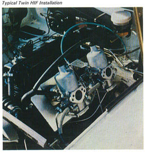
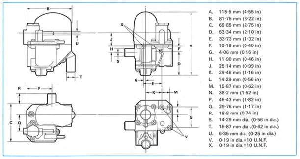
The HIF type is available for both single and multi carburetter applications, complete with all necessary connecting linkage, in throttle bore sizes of 38.1 mm (1.5 in) and 44-45 mm (1.75 in), and may be mounted at any angle from horizontal to 40° down draught inclusive.
Most of the exhaust emission features detailed earlier are fitted as standard on the HIF range.
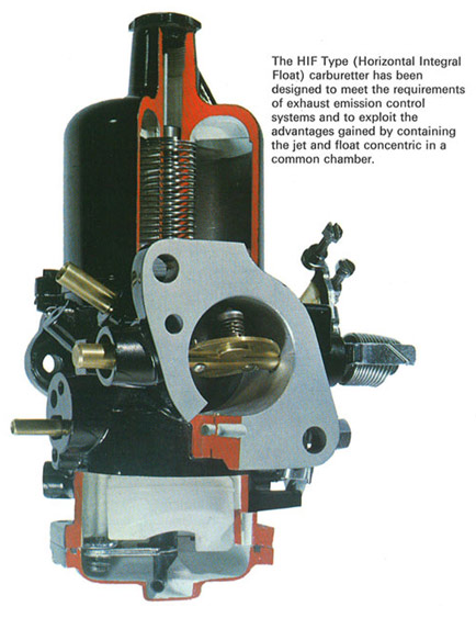
The HIF carburetter is the most recent type to be added to the S.U. range and when equipped with the ball bearing suction chamber assembly represents the very latest in constant depression carburetter design.
AED (Automatic Enrichment Device)
The A.E.D. is a completely automatic auxiliary carburetter. It supplies a mixture, in excess of that provided by the main carburation system, to achieve the degree of enrichment required below normal operating temperature.
The main valve or throttle and the metering system of this self-contained unit are both temperature-sensitive.
Air entering the unit is drawn through a hot air pick-up attached to the exhaust manifold. Bi-metals controlling the main valve and metering needle are influenced by changes in temperature of the incoming air and increase or decrease the flow and strength of the mixture accordingly. A diaphragm and spring assembly acting directly on the jet needle varies the mixture strength in response to changes in manifold depression. To a lesser extent the quantity of mixture is also affected by changes in manifold depression.
This sophisticated device provides efficient starting down to ambient temperatures of -30°C and enables the vehicle to be driven away under these conditions with the minimum waiting period. Having achieved the initial start and drive-away, the A.E.D. will automatically adjust the quantity and strength of mixture it gives to the engine until normal operating temperatures are reached. When this happens the device will have smoothly gone out of operation and will continue to remain so until the temperature falls below a predetermined level. The A.E.D. unit is available for engines up to 4500 cm³ (274.56 in³) capacity.
A.E.D. Features
- Fully progressive starting device
- Self-contained unit
- Quantity and strength of mixture supplied sensitive to operating temperature
- Quantity and strength of mixture supplied sensitive to manifold depression
- Additional fuel reservoir for initial starting
- Two means of adjustment only
- Units preset and adjusters sealed at Factory
AUF 200 Electric Pumps
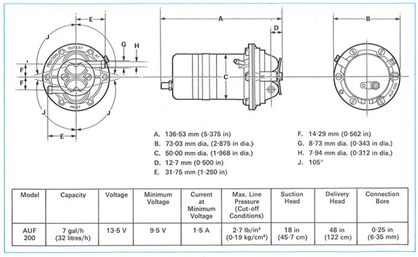
The versatile AUF 200 is the smaller of the current range of S.U. electric fuel pumps. A compact unit of high pressure design, the AUF 200 incorporates inlet and outlet connections adjustable through 210° to facilitate installation. A venting system allows the pump to be fully sealed.
Normally produced in 12-volt form, it is also available in 6-volt and 24-volt versions and a low pressure version, known as the AUF 600, is also produced.
The size and capacity of this pump makes it eminently suitable for use on vehicles in the low and middle power range.
AUF 200 Features
- Freedom of installation:
- Compact dimensions
- Self-contained unit
- Adjustable connections
- Venting system available – allows pump to be fully sealed
- Rapid priming of float-chamber
- Excellent vapour handling capacity
- Twin tungsten contact breaker points.
AUF 300 Electric Pumps
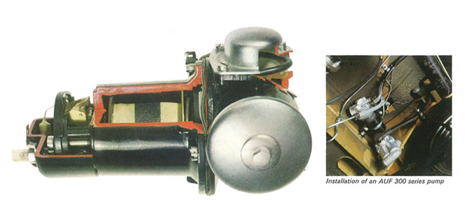
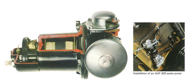
The AUF 300 is a high capacity adaptation of the AUF 200, the pump body having been redesigned to incorporate a flow smoothing unit and an air bottle.
The flow smoothing unit consists of a diaphragm and housing situated above the delivery chamber and outlet passage. Fuel pressure pulsations are damped by the air contained in the housing, resulting in a reduction of flow pressure variations and an increase in output for a given rate of operation.
A large compartment formed in the inlet side of the pump acts as an air cushion and smoothes the pressure pulsations of the incoming fuel; it also prevents high negative pressure being created in the pump body.
AUF 300 Features
- Freedom of installation:
- Compact dimensions
- Self-contained unit
- Venting system available – allows pump to be fully sealed
- High output
- Rapid priming of float-chamber
- Excellent vapour handling capacity
- Flow smoothing on inlet and outlet
- Twin tungsten contact breaker points with condenser protection.

AUF 400 & AUF 500
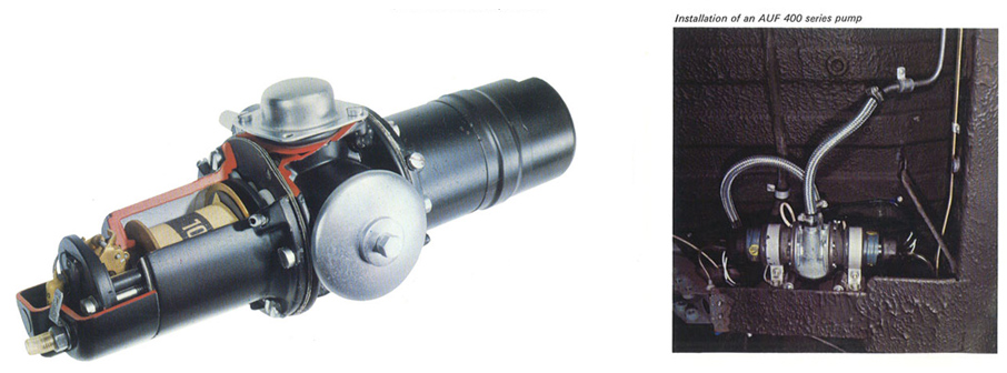
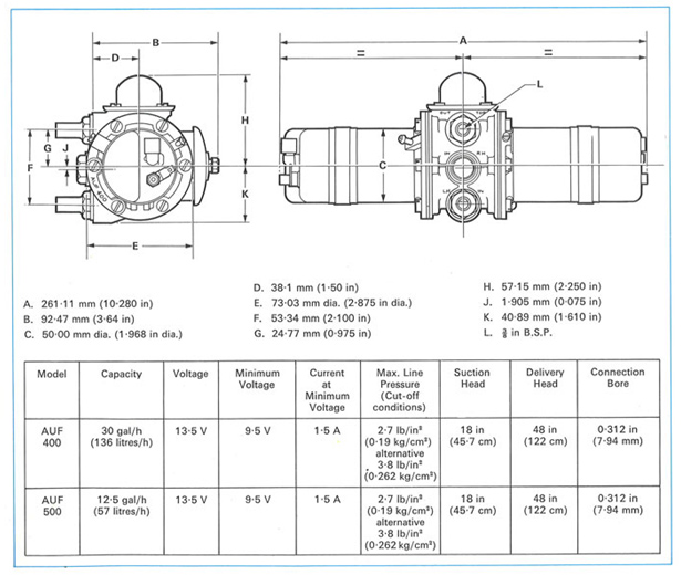
The extra high capacity AUF 400 is basically a dual version of the AUF 300 and has a delivery capability of up to 136 litres/hour (30 gallons per hour).
The pump consists of two coil and diaphragm assemblies mounted opposite each other on a common body casting. Separate pumping chambers, with inlet and outlet valves in each, are fed from a common inlet port and fuel is discharged through a common outlet.
The flow smoothing features of the AUF 300 are incorporated in this pump which has been designed for high pressure applications where the majority of the work is required on the outlet side of the pump.
The standard unit is for use on 12-volt electrical systems but 24-volt versions are also available.
AUF 400 Features
- Freedom of installation:
- Compact dimensions
- Self-contained unit
- Venting system available – allows pump to be fully sealed
- Extra high output
- Rapid priming of float-chamber
- Excellent vapour handling capacity
- Twin tungsten contact breaker points with condenser protection.
Dual Electric Pumps
The AUF 500 dual pump is similar in construction to the AUF 400 but is designed to operate as two separate units for those systems having two fuel tanks, or a main and reserve supply. Two inlet ports on the pump body are for connection to the two fuel tanks. Both sides of the pump discharge into the single outlet provided.
Terminals are provided on each coil assembly for separate connection to the power supply through controls which would normally include a change-over switching arrangement.
AUF 500 Features
- Freedom of installation:
- Compact dimensions
- Self-contained unit
- Venting system available – allows pump to be fully sealed
- Rapid priming of float-chamber
- Excellent vapour handling capacity
- Twin tungsten contact breaker points with condenser protection
- Dual inlet connections, common outlet connection
AUF 700 Mechanical Pump
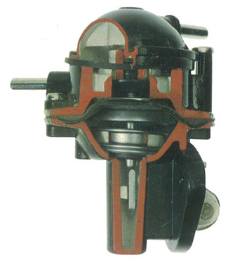
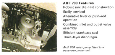
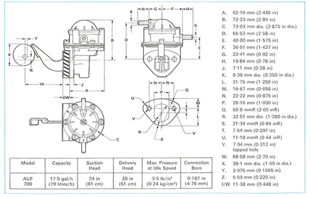
The robust AUF 700 mechanical fuel pump is the latest pump to be added to the comprehensive S.U. fuel pump range. This pump has been designed to operate through a rocker lever or an intermediate push-rod from the camshaft or other engine-driven eccentric. An insulating block interposed between the pump and the engine should be used to protect the pump from excessive heat.
The pump consists of a stirrup operated diaphragm clamped between upper and lower body castings. The upper body houses a unique combined inlet and outlet valve assembly and the inlet and outlet ports. The operating lever, lever pivot, return springs and seal are accommodated in the lower body section.
AUF 700 Features
- Robust zinc die-cast construction
- Easily serviced
- Alternative lever or push-rod operation
- Combined inlet and outlet valve assembly
- Efficient crankcase seal
- Three-layer diaphragm.
The features of the various units described in this leaflet are correct at the date of publication of the leaflet, but the manufacturers reserve the right to vary the features of any of these units with or without notice and at such times and in such manner as they think fit. Major as well as minor changes may be involved. Customers are therefore advised before ordering any unit to ensure that the features of that unit as set out in this leaflet are still up to date.
Therefore, although every effort is made to ensure the accuracy of the particulars contained in this leaflet, neither the Company nor the Distributor or Dealer by whom this publication is issued shall be liable for any inaccuracy in any circumstance whatsoever. This publication shall not constitute in any circumstances whatsoever an offer by the Company to any person.


