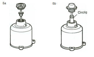
Early type: Hold the piston firmly and pull the suction chamber, taking care not to bend the damper rod, until the bearing retainer is freed from the piston rod (5a). Remove the damper.
Later type: Remove the piston damper. Lift the piston and remove the bearing retaining circlip (5b).
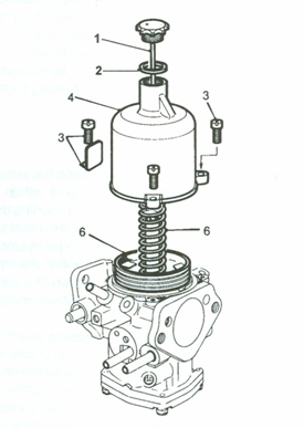
Step 3: Piston Assembly
Separate the suction chamber, spring, and piston assembly (6). Empty the oil from the piston rod.
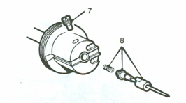
Unscrew the needle guide locking screw (7).
Withdraw the needle, guide, and spring (8).
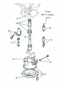
Step 4: Float Chamber & Jet Assembly
Mark the bottom cover-plate and body for reassembly (9). Remove the cover and sealing ring.
Remove the jet adjusting screw and 'O' ring (10).
Remove the jet adjusting lever retaining screw and spring (11).
Withdraw the jet and adjusting lever. Disengage the lever (12).
Remove the float pivot spindle and fibre washer (13).
Withdraw the float (14).
Remove the needle valve (15) and unscrew the valve seat (with filter, on HIF38 & HIF44 only).
Unscrew the jet bearing locking nut and withdraw the bearing with washer (16).
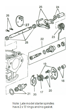
Step 5: Starter Unit & Cam Lever
Note the position of the fast idle cam lever return spring ends (17).
Remove the cam lever retaining nut and locking washer (18).
Hold the return spring toward the carburetter body, prise off the cam lever, and remove the spring (19).
Unscrew the starter unit retaining screws and remove the cover plate (20).
Withdraw the starter unit assembly and gasket (21). Note: On later starter units, the cover plate and starter body are not designed to be separated. This ensures greater accuracy of operation.
Withdraw the valve spindle and remove the 'O' ring, seal, and dust cap (22).
Step 6: Throttle Lever Assembly
Note the location and loading of the throttle lever return spring and remove the spring (23).
Unlock and remove the nut and tab washer retaining the throttle levers (24).
Remove the throttle lever and throttle actuating lever (25) (designs may vary).
Step 7: Throttle Disc & Spindle
Remove the throttle disc retaining screws (26).
Close the throttle and mark the throttle disc's position relative to the flange (avoid the overrun valve). Open the throttle and carefully remove the disc from the spindle (27).
Withdraw the throttle spindle and remove its seals (28), noting their orientation for correct reassembly.