SU Carburetter Company
By P.G.G KNIGHT
INTRODUCTION
THE VAST MAJORITY of modem spark ignition internal combustion engines rely upon carburetters to provide them with the finely atomized fuel/air mixture which is necessary to enable them to perform satisfactorily. It is the function of the carburetter to provide good atomization and the correct mixture strength, under all operating conditions of the engine. The method used to do this in all carburetters is to speed up the velocity of the air by means of a venturi or choke, and to use the consequent reduction of pressure in the venturi to draw fuel from the float chamber through a suitable jet orifice into the air stream. Since the power that an engine can develop is dependent upon the quantity of air consumed, it is desirable that the mixture of fuel and air should be carried out with as little restriction as possible to the overall air flow.
On a fixed choke carburetter the venturi must be sufficiently small to ensure adequate mixing during conditions of low air consumption. On engines that require to operate over a wide speed and power range, it is inevitable that a choke sufficiently small for use with low air consumption will give an excessive depression at maximum air flow. An obvious solution to this problem is to arrange for the size of the choke to be increased at high engine output and decreased for bottom end performance.
GENERAL DESCRIPTION
It is now well over fifty years since the Skinner brothers first introduced their constant depression carburetter. The increasing number of cars using carburetters made to this same basic principle indicate that the idea was sound. The near constant depression, maintained in the carburetter under all operating conditions, is obtained by means of automatic regulation of the choke size. It is sufficiently high to ensure that good atomization is obtained, yet the depression is kept as small as possible in order to maintain engine filling at a maximum. At the same time as the main passage above the jet is varied so too is the area of the fuel jet by means of a tapered' needle, the whole being regulated by the rise and fall of the piston under the influence of throttle opening and manifold depression. This depression is itself dependent on the power requirement of the engine under the conditions at which it is being operated. In this system one jet only is used and the avoidance of multiple jets means that any possibility of flat spots, which may occur during the change- over from one jet to another, is eliminated. Correct jet discharge areas are obtained by the accurate dimensioning of the needle, which must be carefully matched to the requirement of the particular installation.
TYPES OF UNIT
Types of unit in current use are: (I) the H type, (2) the HD type and (3) the HS type. In addition a dual choke instrument designated the DU6 has been manufactured in very limited quantities. This latter type has, however, never been made in large production quantities, nor is it anticipated that it ever will be.
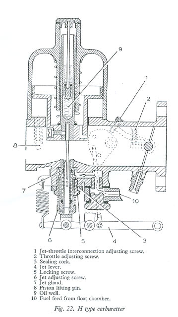
The H type carburetter
This is, perhaps, the most familiar type of S.U. carburetter, being the one which has been in general use for the longest period and therefore in larger quantity than any other type. It is shown in diagrammatic form in Fig. 22.
It consists of body, piston/suction chamber, jet and float chamber assemblies, the fuel being fed from the float chamber through a passageway in the float chamber arm into the fuel passages of the body, and thence through cross drillings in the jet assembly.
It has been made in horizontal and semi-downdraught form with throttle disc sizes ranging from I i in. to 2 in. diameter. As with all current S.U. carburetters its size is designated by the type letter followed by a number. This number indicates the diameter of the butterfly, and is the number of eighths of an inch that the diameter is larger than I in., e.g. an HI instrument has a bore of It in. and an H8 has a bore of 2 in.
The height to which the piston is lifted is controlled by the amount of air passing beneath it. When the piston is at the bottom of its stroke, with the engine idling, opening the butterfly allows the manifold depression to be communicated to the main volume of the body and then through a cross drilling in the lower part of the piston into the suction chamber above the piston. This depression immediately lifts the piston, allowing a mixture of air and fuel to pass the lower side of the piston and relieve the depression. The piston height is therefore stabilized at a depression controlled by the weight of the piston, the load of the piston spring, and: the area .of the large and small diameters of the piston. It will be noted that the underside of the large diameter of the piston is open to atmosphere. The air/fuel ratio is controlled by the diameter of the needle in the fuel jet. The optimum dimensions of this needle are normally found by experiment on an engine dynamometer, and by road testing of the vehicle. Once determined, a profile cam is made to give the desired needle dimensions, and production needles can then be very accurately reproduced to the desired shape.
From this it will be seen that once the correct needle has been specified, the jet has to be set to a datum dimension on the needle to ensure that the desired mixture is obtained throughout the range of the engine operating conditions. This position is set when the carburetter is tuned for idling.
Most S.U. carburetters incorporate a piston damper, the function of which is to restrict the speed of lift of the piston on snap throttle openings, and to allow the piston to fall at its normal speed on throttle closure. This one way damping is obtained by means of a non-return valve situated at the base of the damper.
When the speed of piston lift is retarded an additional air depression is put on the fuel in the jet resulting in an increase in the quantity of fuel discharged. A richer mixture is thus obtained until the piston resumes its position of equilibrium. This enrichment is necessary to provide satisfactory pick-up. The piston damper also improves cold starting and driveability from cold.
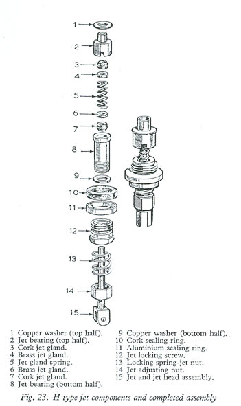
It is of the utmost importance that the fuel jet is assembled concentric with the needle. In order to allow for liberal adjustment the complete jet assembly is manufactured with side clearance between the jet bearing and the carburetter body. Once the assembly has been correctly centred (with the jet full up and the piston resting on the bridge) it is locked in position by means of a large jet locking screw. The components of the H type jet are shown in order of assembly in Fig. 23. On most H type carburetters the float chamber is firmly secured to the body by means of a banjo bolt. On some engines, however, where vibration has led to malfunctioning of the float chamber, it has been found necessary to use a flexible mounting between the float chamber arm and the body of the carburetter. This has been achieved by means of rubber grommets secured by a shoulder bolt, or pillar bolt on later models.
Since the carburetter is of the constant vacuum type the depression at the jet never falls below its normal operating value, and it is for this reason that variations of fuel level in the float chamber are unimportant.
On many cars it is found desirable to use vacuum operated ignition advance to obtain optimum part throttle consumption figures. The take-off point for this vacuum is arranged slightly to the air intake side of the butterfly, and in such a position that opening the butterfly allows the throttle disc to pass over the vacuum take-off point so that it then communicates with the manifold depression. By this means the vacuum is small at the distributor during idling and full throttle conditions, and is large at part throttle, being at a maximum when the throttle is open a few degrees.
Enrichment of the mixture for cold starting and running is obtained by lowering the jet. The lever used to carry out this function 1s also provided with an additional link which operates the cam and opens the butterfly by a pre-determined amount. Some lost motion is built into this system, usually by means of additional clearance at one of the pivot points. This allows the throttle to be opened a few degrees before the jet is dropped, to provide for the semi-warm condition when no additional enrichment is required but the engine has not yet warmed up sufficiently to prevent the engine stalling at idling conditions.
One other item now fined to all S.U. carburetters is the piston lifting pin. This is used when the engine is not running, to lift the piston assembly for the purpose of checking that the needle is correctly centred and that the piston falls freely. It is also used to lift the piston a small amount when the engine is idling in order to check the mixture strength.
On earlier models, before the fitting of the lifting pin, a hole was made in the carburetter body below the large diameter of the piston. The piston could thus be raised by means of a wire inserted through this hole.
The HD Type
The HD type of carburetter (Fig. 24) is very similar to the H type, the main difference being that the fuel to the jet is sealed by means of a diaphragm in place of cork glands. A separate by-pass idling passage is incorporated and the enrichment mechanism is re-designed.
This type of unit is made in three sizes, HD4 (1 tin.) HD6 (1i in.) and HD8 (2 in.), and all can be supplied as either horizontal or 30° semi-downdraught units but no flexible mounting for the float chamber is available.
Whilst the jet cantering is, in general, carried out as on the H type, it is less accessible and the float chamber and diaphragm sandwich pieces both have to be removed before the jet bearing locking screw (21) can be slackened or tightened. Once properly centred, however, the jet is well protected against any extraneous blows and is therefore unlikely ever to require further adjustment in this respect.
In order to minimize the likelihood of fuel entering the vacuum advance unit on the distributor, the vacuum ignition take-off point is mounted at the top of the butterfly, and for this reason the butterfly direction of opening is opposite to that of the H type.
For idling the butterfly is held completely closed and the volume of charge required is regulated by a metering valve (18) situated at the side of the body. The setting of the jet is by means of a pivoted fork (7) controlled by an external screw (8) and the additional throttle opening required for fast idling is obtained through a sliding rod (13) operating in a bearing cast into the body.
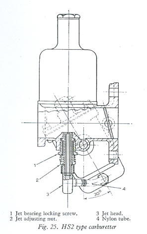
The HS type
This type of instrument (Fig. 25) is also similar to the H type, the main difference is, again, in the method of supplying the fuel from the float chamber to the jet. In this instance a nylon tube (4) is employed, connecting the base of the float chamber to the bottom of the jet so that, as with the HD type, cork gland washers are not required. The direction of opening of the butterfly is the same as on the HD type, the vacuum advance connection being mounted above the throttle spindle.
The float chamber assembly differs from the H and the HD types both in the method of mounting and in the type of float used. The float chamber is bolted horizontally through the body of the carburetter and can be mounted either flexibly (on rubber) or rigidly. Provision is being made for mounting at 30°, 20° or horizontally.
When a brass float is used it is guided by flutes on the wall of the float chamber, instead of by means of a stud passing through the middle of the float. More recent carburetters have nylon float anchored to the lever arm. The float chamber lid is attached by means of three small screws. Fuel connections to the lid are by push-on connections.
HS carburetters are available as left or right hand units of 11/4 in., 11/3 in. or 13/4 in. throttle diameter. 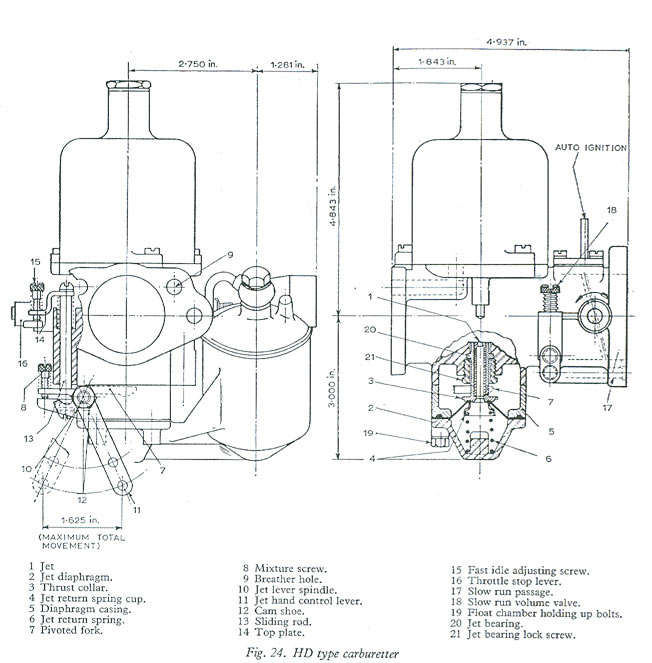
These dual choke carburetters of It in. diameter throttle bore were used almost exclusively on the Coventry Climax 11/2 litre twin cam engines. New units are not now available.
Whilst they work on the basic S.U. principle they have an additional full throttle - diaphragm operated weakening device. It was necessary to introduce this weakener to overcome excessive mixture spread between full throttle and part throttle conditions. Without this device it was found that correct part throttle tuning produced an over-rich condition at full throttle, and conversely, correct full throttle tuning resulted in an over-weak mixture at part throttle.
One other feature on these instruments was the positioning of the float chamber between the two chokes of the carburetter. This necessitated the use of a narrow rectangular doped cork float, which is satisfactory in petrol but cannot be used with methanol blends.
SETTING OF S.U. CARBURETTERS
Once the correct carburetter needle and spring have been established, tuning of the S.U. carburetter is normally confined to correct idling adjustment. As a preliminary to making any alteration of this setting it is, however, advisable to ascertain thin the ignition system is in good order and correctly set, that the engine is in good mechanical condition, i.e. tappet clearances, compressions, etc., and that the carburetter is mechanically sound and its jet correctly centred. It is also necessary that the engine should have been run to obtain its normal working temperature.
Setting of H type carburetters After the correct operating temperature has been attained, close the throttle completely by unscrewing the throttle adjusting screw until it is just clear of its stop. Open it by screwing down this screw 1 1/2 turns.The piston and suction chamber should now be removed and the mixture control wire disconnected. Screw the jet adjusting nut until the jet is flush with the bridge of the carburetter, or 'full up' if this position is not obtainable. Replace the piston and suction chamber assembly and check that the piston falls freely on to the bridge of the carburetter. Turn down the jet adjusting nut two complete turns (12 flats). Re-start the engine and adjust the throttle adjusting screw to give the desired idling speed as indicated by the ignition warning light. Turn the jet adjusting nut until me fastest idling speed is obtained consistent with even firing. During this adjustment it is necessary to ensure that the jet is pressed upwards and is in contact with its adjusting nut. As the mixture is adjusted the engine will probably run faster; it may therefore be necessary to unscrew the throttle adjusting screw a little in order to reduce the speed.
Now check the mixture strength by lifting the carburetter piston (by means of the lift pin situated on the side of the carburetter body) by approximately 1/32 in., when if
(1) The engine speed increases and continues to run faster, the mixture is too rich.
(2) The engine speed immediately decreases, the mixture is too weak.
(3) The engine speed momentarily increases very slightly, the mixture is correct.
When the mixture is correct the exhaust note should be regular and even. If it is irregular, with a splashy type of misfire and colourless exhaust, the mixture is too weak. If there is a regular or rhythmical type of misfire, together with a blackish exhaust, then the mixture is too rich. Reconnect the mixture control wire with approximately 1/16 in free movement before it starts to pull on me jet lever. Set the mixture control knob on the dash panel to its maximum movement without moving the carburetter jet (about 5/8 in.) and adjust the fast idling cam screw to give an engine speed of between 800-1000 rev/min (when hot). When setting the slow running of a vehicle, consideration of the type of power unit fitted should be made. Engines with large valve overlap will require a fast idle and it will be difficult to obtain an extremely smooth tickover.
Setting of HD and HS carburetters
The technique of setting these carburetters follows the same general principle as with the H type. It is, however, necessary to become familiar with the different means of carrying out the various adjustments as previously described in this paper.
Setting multi-carburettor layouts
When setting two or more S.U. carburetters on an installation the same general principles apply as those described for me setting of a single layout. It is, however, important to remember that most manifolds employing more than one carburetter are manufactured with balance pipes which interconnect the various manifold passageways from each carburetter. Because of this an adjustment made to one carburetter will influence the mixture of all cylinders to a greater or less degree.
More recent multi-carburetter installations of the HS type, and some employing HD units, vary from the usual installations of H type carburetters in one important detail. On these installations the various throttle spindles are not connected directly to each other, but are operated through a lost motion linkage. This system has the advantage of allowing fast idle to be achieved without movement of the accelerator controls, thus reducing the load on the choke control knob. In the case of the HS type it also allows individual slow running screws to be adjusted without the necessity of undoing throttle clamps.
Before setting the carburetters, the engine should be run long enough to obtain its normal operating temperature, then the clamping bolts on the throttle spindle connections slackened and all throttles fully closed by unscrewing the throttle adjusting screws. The piston and suction chambers should be removed and the jet control linkage disconnected by removing the fork swivel pins. The jet adjusting nuts should be screwed up until each jet is flush with the bridge of its carburetter, or as near as possible. All jets must be in the same position relative to the bridge of their respective carburetters.
The piston and suction chamber assemblies should now be replaced and the pistons checked for free fall. The dampers must be topped up with oil and the damper caps replaced after checking that the proper type of damper cap is fitted. The jet adjusting nut should now be turned down two complete turns (12 flats), the engine restarted and the throttle adjusting screws set to give the desired idling speed by moving each throttle screw an equal amount. Using a length of tube the hiss at the mouth of each carburetter must now be checked by ear and the throttle adjusting screws turned until the intensity of the hiss is similar on all intakes. This will synchronize the throttles.
When this is satisfactory the mixture should be adjusted by screwing the jet adjusting nuts up or down by the same amount, until the fastest idling speed is obtained consistent with even firing. During this adjustment it is necessary to ensure that the jets are in contact with the adjusting nuts.
On obtaining the correct mixture adjustment the engine will probably run faster, and it may therefore be necessary to unscrew the throttle screws a little, each by the same amount, to reduce the speed. The mixture strength of each carburetter should be checked, one carburetter at a time, by the method previously described in the section on tuning single H type carburetters. When all the carburetters have been checked and any adjustment made, it is necessary to re-check because of the influence of each carburetter on all cylinders. Nevertheless it must be understood that the indications given by lifting a piston if in. apply primarily to the carburetter to which the piston belongs, and it is on this carburetter that any further adjustment should be made.
On obtaining the correct mixture adjustment the engine will probably run faster, and it may therefore be necessary to unscrew the throttle screws a little, each by the same amount, to reduce the speed. The mixture strength of each carburetter should be checked, one carburetter at a time, by the method previously described in the section on tuning single H type carburetters. When all the carburetters have been checked and any adjustment made, it is necessary to re-check because of the influence of each carburetter on all cylinders. Nevertheless it must be understood that the indications given by lifting a piston if in. apply primarily to the carburetter to which the piston belongs, and it is on this carburetter that any further adjustment should be made.
When the setting is correct, the throttle spindle interconnection clamping bolts should be tightened on the couplings. The jet control linkage and mixture control knob can be re-connected in the manner described for a single carburetter.
Adjustment of Jet and Throttle Interconnection
With the cam-type jet and throttle interconnection (shown dotted in Fig. 22) or its preceding rocker type, the outer adjusting screw (1) should be about 1/64 in. away (thickness of a visiting card) from the cam face or rocker face when the engine is warm and idling on a closed throttle; with the rocker type this figure should not be exceeded, but with the cam type a larger gap can be used if desired. If the jet adjusting nut is altered in position substantially then the screw (1) may also need suitable readjustment.
Piston Springs
On 1 1/4 in., 1 1/2 in. and 1 3/4 in. diameter horizontal carburetters, the red (4t ounce) spring is normally used for initial testing and in most installations this load of spring will be effective, assuming that the size of carburetter has been correctly chosen. When the correct spring is fitted it is usual to obtain full piston lift at full throttle and at approximately three-quarters of the maximum rev/min. If the absolute maximum of power is required, however, it is more usual to choose a somewhat larger carburetter, which will not obtain full piston lift until nearer maximum rev/min.
Oil Dampers
After the carburetters have been correctly set it is necessary to check that the oil damper reservoir in the piston rod has sufficient oil. This operation should, in any case, be carried out periodically at about every three months, and it is usual to use an oil of grade SAE 20 (it should be no thicker than SAE 30). The operation is not a critical one; simply unscrew the damper unit and pour oil into the hollow piston rod until it is within t in. from the top of the rod.
Float Chamber Fuel Level
The fuel level on an S.U. is not critical, and need not be treated with meticulous accuracy-the normal level is 3/8 in. under the rectangular inner facing known as the jet bridge, but this is rather difficult to observe even with the suction chamber and piston removed and the jet fully dropped. However, a simple mechanical check can be made, and this consists of sliding a certain diameter of check rod between the lid face and the inside curve of the forked end of the hinged lever when the needle valve is in the 'shut off' position. The size of this rod for both the 1 7/8 in outside diameter smaller float chamber and the larger one of 2 1/8 in outside diameter is 7/16 in. On the HS type of float chamber a 5/16 in. rod is used with a brass float, and a 1/8 in. rod when the hinged nylon float is fitted. If the hinged lever fails to conform within 1/32 in. of these check figures it must be carefully bent at the start of the fork section, in the necessary direction for correction, taking care to keep both prongs of the fork level with each other. It must be emphasized that it is not advisable to alter the fuel level unless there is trouble with flooding; and although a too high level can cause slow flooding, particularly when a car is left ticking over on a steep drive, it should be remembered that flooding can also be caused by grit in the fuel jamming open the needle valve, or undue friction in the float gear, or excessive engine vibration, or a porous float.
Effect of Altitude and Climatic Extremes on Standard Tuning
he standard tuning employs a jet needle broadly suitable for temperate climates from sea level up to 6000 feet. Above that altitude it may be necessary, depending on extremes of climatic heat and humidity, to use a weaker tuning. The factors of altitude, extreme climatic heat and humidity each tend to demand a weaker tuning and a combination of any of these factors would naturally emphasize this demand. Tills is a situation which cannot be met by hard and fast factory recommendation owing to the wide variations in the conditions existing, and in such cases the owner may have to do a little experimenting with alternative weaker needles until one which is satisfactory is found. To assist in this matter it is normal for a recommended weak needle to be listed.
BASIC INITIAL TUNING OF S.U. CARBURETTERS
A correctly tuned carburetter on a perfect installation should supply its engine with the weakest mixture capable of providing maximum power at full throttle, and minimum fuel consumption for all part throttle running of the engine. For a given carburetter piston lift and average air flow through the instrument, heavy air pulsations give rise to an enrichment of the mixture strength due to the continuing flow, by inertia, of fuel through the jet after the flow of air has diminished.
Under full open throttle conditions the pulsations of air flow through the carburetter are large: Their magnitude depends on many factors, including engine speed, length and cross-sectional areas of the induction manifold, valve timing, the number of cylinders served by each inlet port and exhaust system design, to mention only a few.
Any closure of the throttle damps down the degree of pulsation and therefore weakens the mixture. It is because of this that it is possible to obtain a needle setting that will give the desired fuel flow throughout the operating range, thus achieving the correct mixture spread between full and part load running.
Balance Pipe Size
Fortunately the optimum conditions of mixture spread are closely approached on most four cylinder engines using a single S.U. carburetter. It is also possible, by choosing the right size of balance pipe, to arrange for the degree of air pulsation at the carburetters to give the correct full to part throttle mixture spread on multi-carburetter multi-cylinder engine installations. This is also true of twin installations on four cylinder engines.
In some instances the largest practical size of balance pipe is insufficient to prevent the mixture spread from being slightly greater than the optimum. In such cases it is desirable to obtain optimum results on part throttle, allowing the full throttle con condition to remain slightly rich. Providing tills full throttle mixture is not so rich as to cause a fall off in power this condition can be tolerated, since in practice the only full throttle speed at which the car can be driven continuously is its maximum speed, either on the level or up an incline. Under these conditions (which are comparatively rare) the carburetter piston is either at full lift or approaching full lift, so that the diameter of the needle used to meter fuel is other than that used for part throttle conditions. Thus it is possible in such cases to tune the needle for optimum part throttle and maximum speed results, the only penalty being the slight extra enrichment at low speed, full throttle. Results show that this has negligible effect on overall road consumption figures and is actually beneficial under drive away from cold conditions.
Weakening Device
Engines with six or more cylinders employing one carburetter usually have insufficiently heavy full throttle pulsations to give the required full throttle mixture if set correctly for part throttle. It is therefore necessary to tune such installations for correct mixture at full throttle, economy at part throttle being provided by means of a weakening device designed to provide a small depression on the fuel in the float chamber. Tills depression is arranged to operate at part throttle by means of a pipe taken from the edge of the butterfly in a similar manner to that normally applied for ignition partial vacuum advance. The pipe draws air through a venturi from the float chamber, replacement air entering the chamber through a fixed orifice of calibrated size, to give the desired reduction of air pressure on the fuel in the float chamber, thus diminishing the fuel flow through the jet. The function of the venturi member is to limit the amount of air that will pass through the device so that the maximum weakening effect is obtained when the throttle is closed by a relatively small amount from the full throttle position.
New Installations
When a new engine installation is envisaged the desirable sequence of tuning events is: firstly to tune the engine for all running conditions on a test brake, secondly to re-check the installed engine on a car by means of a roller dynamometer, thirdly to carry out full road consumption and performance checks on the vehicle, fourthly to carry out cold start and drive away tests and finally to use the car for a prolonged period on all types of journeys and under all climatic and geographic conditions.
For the initial bench testing of a new engine type 'hand controlled' (or variable mixture) settings are used in order that the effects of camshaft, ignition, manifold, compression, exhaust system and any other changes can be assessed. Once all the relevant engine particulars have been finalized, including the car air intake silencer and exhaust systems, serious carburettor tuning can be commenced.
The process of obtaining the correct needle dimensions for an S.U. carburetter installation is a comparatively simple one, and is described later in tills paper.
Roller Dynamometer Tests
Since the installation conditions of the vehicle itself may vary from those of the test bed it is helpful to install the whole vehicle on the roller dynamo meter when a further check, accompanied by any necessary tuning alterations, can be carried out. Normally these checks are made at full throttle and road load conditions. Because of the difficulties of determining accurately the losses through the vehicle transmission and tyres when installed on the roller dynamometer, the road load curve for this test is normally obtained by means of a vacuum gauge fitted to the induction manifold. Manifold depression is noted on the road at constant speeds throughout the range and the dynamometer loads required to match these readings are recorded. It is important that carburetter and ignition settings are in no way altered after the road run and before installing the vehicle on the dynamometer.
Fuel for testing on the roller dynamometer is supplied through the car fuel pump system, and this is a check that the flow is adequate. A test should also be carried out with the correct carburetter dampers fitted to ensure that they in no way affect the tuning.
Road Tests
Both engine and dynamometer tests are carried out with the one object of obtaining optimum performance from the vehicle on the road. It is therefore most important that the results are verified by a full road test. Ideally this should be carried out on a proving ground such as that of M.I.R.A. at Lindley.
The normal test procedure is to carry out acceleration and set speed fuel consumption checks using the needle setting found to give optimum results on the dynamometer. That these are, in fact, the best figures is ascertained by repeating both tests using first slightly richer and then weaker needles. Alternatively, similar results can be obtained by setting the jet first richer and then weaker.
Manifold Heat
If it is found that the richer needle improves acceleration figures at the expense of road load consumption, this can indicate that the hot spotting arrangements for the manifold are insufficient and may lead to alterations to the manifold, and subsequently the necessity of further tuning.
On multi-carburetter installations it may be possible to overcome an increase in part throttle consumption by using a smaller balance pipe, thereby increasing the mixture spread and allowing the use of weaker needles.
Another effect of insufficient heat on the manifold is the necessity to set the slow running rich in order to avoid flat spots on 'opening up'. By so doing the walls of the manifold are allowed to remain damp during the overrun and idling conditions and throttle response is good. The penalties of doing this are firstly, difficulty in maintaining consistent idling, particularly when the engine is really warm, and secondly some sacrifice of overall fuel consumption, due to the wastage of fuel during idling and overrun conditions. There may also be a tendency for the mixture to 'pile up' rich during prolonged idling. Reluctance to incorporate adequate hot spots is often encountered" on the part of engine manufacturers because of "the possibility of losing power due to the lowering of volumetric efficiency. If the hot spotting arrangements are kept to the minimum, and the heat is applied to vaporize the fuel, there will be practically no reduction in volumetric efficiency and it will result in the considerable benefits mentioned above, together; with improved distribution. The net result may well be a gain of power.
Cold Starting
In addition to the above road tests it is desirable to check the cold starting under severe conditions, and for this purpose the vehicle should be subjected to refrigeration tests.
Under conditions of cold starting at very low temperatures it is not possible to vaporize the fuel to any large extent, and effective starting depends primarily on the ability to distribute liquid fuel evenly to all cylinders. Merely providing a sufficient quantity of fuel from the carburetter is not enough, since an excessive quantity of fuel in one cylinder will wet the ignition plug and put it out of action before the right mixture is available in the remaining cylinders. Good cold starting ability relies very largely on the design of the induction manifold, which should provide that liquid fuel poured into the manifold at the carburetter flange will find its way in approximately equal proportions to all cylinder ports.
Whilst it is possible to check cold starting ability in the refrigerator it is unfortunately not possible to obtain information on the 'drive away' qualities of the car. This can best be checked by shipping the vehicle to a country where the required ambient conditions actually exist.
At this stage, with all the obvious deficiencies presumably eliminated, as many cars as possible should be fitted with the proposed production layout and extensive driving carried out under all conditions of terrain and climate. The cars should be driven by individuals with different driving techniques and not only by trained test drivers. These tests have a fair chance of showing up unsuspected defects (and not only of carburetter tuning) before the vehicle is in the hands of the customer.
NEEDLE DETERMINATION
To find the dimensions of a needle that will match up to the optimum results obtained by varying the jet drop during tests, it is first of all necessary to plot out the test needle.
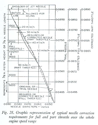
The needle diameters in thousandths of an inch are plotted on the horizontal axis and the needle length in 1/8 in. increments on the vertical axis, conforming with the method used to dimension needles in the needle charts. The piston heights corresponding to various speeds can then be super- imposed on the vertical axis.
All needles with the same profile over the first 1/8 in. of their length will require the same jet drop for idling, thus allowing an immediate assessment to be made of the effect on mixture of the remaining dimensions. If these idling dimensions -are not maintained accurate assessment of the effects of different needles cannot be made until the alteration of the jet drop necessary to give the same fuel discharge at idling has been established.
In order to maintain a constant idling setting when using different needles every effort is made to maintain the shoulder and 1/8 in. dimension at standard figures, i.e. 0•089 in. and 0•085 in. for 0•090 in. jets, 0•099 in. and 0•095 in. for 0•100 in. jets and 0•124 in. and 0•1205 in. for 0•125 in. jets.
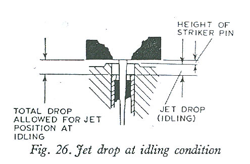
The position of jet drop below the bridge, and the piston lift above, are determined at idling conditions. Assuming that the idling dimensions will be retained this jet drop (shown in Fig. 26) must be added to piston lift at all readings to establish the actual distance of the metering diameter from the shoulder of the needle.
Needle correction
To determine the required dimension of the needle at any given engine speed and load the piston height and jet drop necessary for optimum fuel flow at that speed and load must first be established.
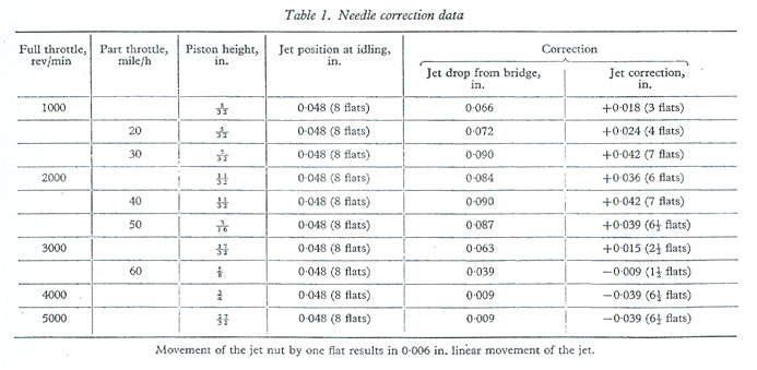
The jet drop at idling must then be subtracted from the actual jet drop to give the vertical correction. If the result is positive, i.e. some jet drop still remains, indicating that a richer setting is required, then the diameter of the required needle at that particular piston height is the- diameter of the original (or trial needle) at the point given by the piston height plus the vertical correction. If the result is negative, i.e. the jet drop at that piston height is less than the jet drop at idling, indicating that a weaker setting is required, then the required diameter is at the point given by the piston height minus the vertical correction. Figs 27a and 27b show the method for correcting a diameter on the needle for rich and weak conditions respectively. Fig. 28 shows a needle corrected for both full and part throttle requirements, and Table 1 shows the method of establishing the required dimensional changes.
Once the new dimensions have been established either an existing book needle should be found or an experimental one made to suit. The test should now be repeated using the revised needle with the jet set for tickover. This will show up any unexpected fuel discharge characteristics which may have resulted from any large variations of jet drop necessary to obtain the desired results with the initial needle. Should this be the case it will be necessary to carry out further tuning using the revised needle as a datum.
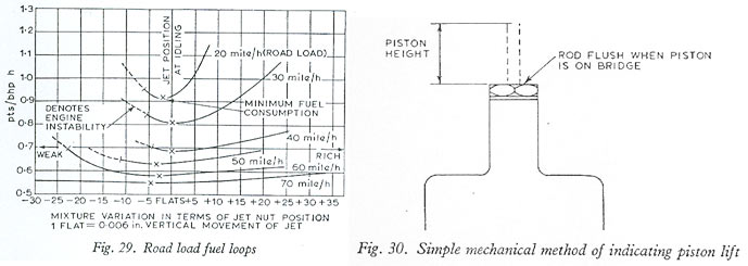
Part load figures are best checked by running a series of partial loops at road load, 3/4 load, 1/2 load and 1/4 load and various engine speeds, the variations in fuel flow being made by adjusting the jet setting either above or below the idling position (see Fig. 29). All these tests should be carried out using hand controlled ignition and complete air intake and exhaust systems.

Piston Lift Measurement
So far it has been assumed that either an engine test brake or a roller dynamo meter is available for the purpose of needle determination. In either of these cases it is a comparatively simple matter to measure piston lift and jet drop.
A very effective method of checking piston lift is by means of a rod inserted in a hole drilled vertically through the suction chamber cap. This is then cut off flush with the top of the cap while the piston is resting on the carburetter bridge. Care must be taken to ensure that this rod does not introduce undue friction. When this method is used on fully dust proofed carburetters, which are internally drilled to allow equalization of air pressure between the damping chamber and the inside of the suction chamber, it is important that air is not allowed to escape past the indicator. A serious leak here will reduce the pressure difference across the piston, but an adequate seal can usually -be made by use of a little oil on the rod. The principle is shown in Fig. 30.
Many instances occur of the necessity for tuning vehicles when neither test bed nor dynamometer is available. In such cases satisfactory results can be obtained by road testing, during which the jet position can be ascertained through the movement of the jet control cable. Measuring the life of the carburetter piston, however, presents a rather more difficult problem.
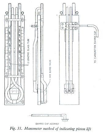
A very satisfactory solution is the use of a manometer using a liquid of low specific gravity (such as paraffin), one side being connected to the piston damper cap by means of a small bore tube (see Fig. 31). Movement of the piston rod displaces the air in the connecting tube and thence the liquid in the manometer. The bore of the glass tube used for the- manometer can be chosen to give the desired magnification of piston movement. As the car is driven so will the underbonnet temperature vary, thus altering the volume of air in the connecting tube. Provision must therefore be made for the instrument to be 'zeroed' at any time and this is achieved by the insertion of an external valve in the air tube. Before taking a reading of piston lift it is only necessary to release the accelerator pedal (allowing the piston to fall on to the bridge of the carburetter) and to momentarily open the air valve allowing the manometer to return to its zero position.
CHOICE OF CARBURETTER SIZE
The correct size of carburetter to be used on any particular installation depends on many factors. As a very rough guide, for single carburetter installations on four cylinder engines it is normal to use a 1 1/4 in. diameter unit for powers up to 45 bhp, 1 1/2 in. diameter from 45 to 64 bhp, 1 3/4in. diameter from 65 to 85 bhp and 2 in. diameter from 85 to 110 bhp.
In deciding on the right size it should be remembered that the primary factor to consider is the maximum velocity of air through the unit at any time during the induction cycle, and not the mean velocity. From this it follows that for a given engine capacity or power a single cylinder engine will require a larger instrument than a twin, which will need a larger carburetter than a four cylinder and so on. It also follows that the greatest volume of air that can be passed by a carburetter for any given maximum depression occurs when it is used in conjunction with a centrifugal blower. Under these conditions peak depression is synonymous with mean depression.
When considering multiple carburetter installations, the general reasoning outlined above will apply, but the size of balance pipe used to connect the various induction tracts must also be taken into account. A large bore balance pipe allows each carburetter to contribute appreciably to the breathing of the cylinders which are served primarily by other units. A small bore balance will allow only a small contribution. It is for these reasons that it is not always possible to forecast precisely the size of carburetter that is required. Inevitably the final decision must be taken after preliminary bench tests have been carried out and the final choice is often influenced by the financial aspect. Frequently the additional cost of a larger unit has to be considered against possibly only a slight gain in horsepower.
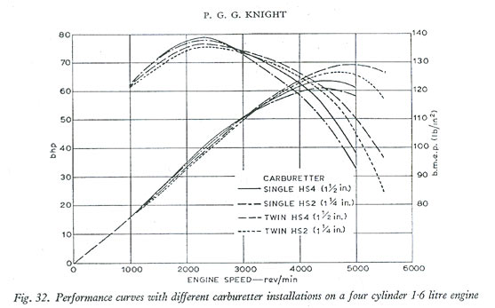
Fig. 32 illustrates the results obtained using single and twin carburetter installations of different sizes on a four cylinder engine of 1.6 litres capacity.
INDUCTION MANIFOLD DESIGN
Even if a carburetter is capable of providing the correct air fuel ratio at optimum depression, this is only one of the conditions necessary for good induction. The satisfactory breathing of an engine will always depend, to a very large extent, on the design of the remaining part of the induction system, as well as the exhaust system.
An induction system comprising one port and carburetter choke per cylinder is capable of giving perfect distribution, and lends itself to the use of ram pipes which can be tuned to give optimum power at any given engine speed. Whilst it may be possible to raise the overall b.m.e.p. with such a system, it will be found that different lengths of pipe, whilst raising the power locally, may lead to a slight fall off in power at other speeds.
Very similar results can be obtained by the use of one choke serving two cylinders, but in this type of installation the major effective ramming must be carried out in the induction pipe between the carburetter and the ports.
Where possible the two cylinders served by anyone carburetter should have equally spaced firing impulses. Whilst this arrangement may be possible on four cylinder engines it is extremely difficult to achieve with six cylinders. Fortunately excellent results are obtainable even when the firing impulses are uneven.
Some slight advantages may be obtained by the use of air trumpets on the air intake side of the carburetters, and these are particularly helpful in collecting blowback. This will prevent wastage of fuel, and possibly bad distribution due to blowback being consumed by adjacent carburetters. This type of installation is found to give excellent distribution, but the necessary length of induction passage is often difficult to accommodate, particularly on six cylinder engines.
Induction systems employing two carburetters give good breathing characteristics and distribution, without the use of excessive heat. Some effective ramming is possible by extending the individual induction passages between the main gallery of the induction pipe and the ports. Sufficient heat must be applied to the main gallery to ensure that fuel separation does not occur before the fuel/air mixture enters the individual passageways leading to the ports.
To install a single carburetter on a six cylinder engine and to obtain good distribution presents a difficult induction pipe problem. Good distribution can be achieved, but to do so usually involves very considerable experimental work on the pipe, and whilst It may not be difficult to obtain satisfactory results at one set speed, to do so throughout the speed range is a more formidable problem. Fig. 33 indicates the type of full throttle results that may be obtained with various carburetter installations on a six cylinder engine.
Four cylinder induction pipe design problems are similar, although the likelihood of poor distribution when using a single carburetter is less.
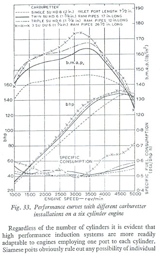
Regardless of the number of cylinders it is evident that high performance induction systems are more readily adaptable to engines employing one port to each cylinder. Siamese ports obviously rule out any possibility of individual port ramming; they introduce the likelihood of one cylinder robbing its neighbour and in consequence make for imperfect distribution. Three Siamese ports on a six cylinder engine make it impossible to use twin carburetters, since there is no way of arranging for a balance pipe restriction.
ACKNOWLEDGEMENTS
The author would like to thank the S.U. Carburetter Co. Ltd for permission to publish this paper, and to acknowledge the help given by his colleagues during its preparation.