Description
The automatic Enrichment Device is a fully automatic auxiliary carburetter for providing an internal combustion petrol engine with the necessary fuel/air mixture in excess of that supplied by the standard carburetters whilst the engine is below its normal temperatures.
It consists of a small carburetter complete with float-chamber and a throttle in the form of a valve opened or closed by the deflection of a temperature sensitive bi-metallic strip.
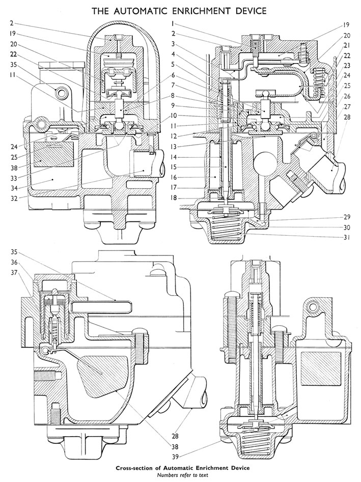
Referring to the diagram to the main valve (10) and its seating (13) form the orifice controlling the volume of fuel-air mixture admitted to the engine.
The main valve is connected to the main bi-metal (22) by spindle (6) which slides freely in the low friction carbon bush (8). By this means the valve orifice is determined by the temperature of the main bi-metal (22), the lower the temperature the larger the orifice.
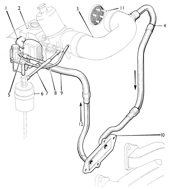
The outlet pipe (32) is connected to the inlet manifold and the inlet pipe (28) is connected to a hot air pick-up on the exhaust manifold so that filtered air drawn through the device via the carburetter elbow is heated as the engine warms up.
The main bi-metal (22) is attached to the heat shroud (20) which serves as a heat storage and also as an adjustable member for the main valve, being loaded down by spring (21) into grooves (23) formed in the valve body (11) and abutting against the adjusting screw (1).
The main valve (10) is prevented from being drawn down by manifold depression on its seating by the diaphragm (25) which is subjected to the depression in the balance chamber (24). This depression is provided by the matching of the two orifices (33) in the main valve and the orifice (9) in the valve body.
The fuel orifice (18) is situated at the lower end of the jet tube (14) surrounding which is the fuel well (16). This is filled with fuel whilst the device is out of action via the fuel orifice (18) and the well orifice (17) in the side of the jet tube, and is discharged via the well orifice immediately after the engine is started from cold.
The needle diaphragm (30) in conjunction with the diaphragm spring (31) raises or lowers the tapered fuel needle (15) in response to changes in manifold depression, the lower position of the needle, or normal idling position being established when the circlip (4) rests on the upper face of the adjusting nut (5) under the influence of spring (7) and the upper position of the needle coming to rest against the secondary bi-metal (3) so that at low temperatures the needle is withdrawn further out of the fuel orifice.
Fuel enters the float-chamber (34) via fuel pipe (35) and the fine mesh nylon filter (36) to the viton-tipped and spring-loaded float needle (37) which in conjunction with the float (38) controls the level of fuel in the float chamber.
A drilled passage (39) feeds fuel to the fuel orifice.
Operation
Assuming a cold engine, the main valve (10) will be open to a degree determined by the temperature of the main bi-metal (22), the fuel needle (15) will be raised by the diaphragm spring (31) until it restrained by the second bi-metal (3) and the fuel well (16) will be filled to the level of the fuel in the float-chamber.
On cranking the engine air is drawn past the lightly spring-loaded air valve (26) through the main valve seating (13) and into the inlet manifold. Fuel is drawn into the engine through the fuel orifice (18) temporarily enlarged by the lifted needle (15) also through the well orifice (17) and up the jet tube (14) to the main valve (10) producing a very rich mixture to wet the inlet manifold rapidly and so shorten the cranking time. When the engine runs, manifold depression acting via passage (29) draws down the needle diaphragm (30) and allows the spring (7) to lower the fuel needle to its normal idling position. The increased manifold depression also draws the main valve (10) slightly towards its seating due to small out-of-balance forces acting on the valve and its diaphragm. The engine will then run at the required speed as sett by the adjusting screw (1) the mixture strength being temporarily increased by the discharge from the fuel well (16). When the well is emptied, the well orifice (17) acts as an air bleed to the jet tube, air being drawn into the fuel well via passage (29) from the bi-metal chamber (19).
As the engine temperature rises heated air is drawn through the device, a proportion of this passes through the bi-metal chamber via passage (27) and orifices (9) and (33) raising the bi-metal temperature and progressively closing the valve until the full working temperature is reached. At this point the valve will be fully closed but subsequent running will induce sufficient heated air to be drawn through the bi-metal chamber to maintain the bi-metal temperature and keep the main valve closed.
Before running temperature is extra enrichment is needed for acceleration. This provided in response to falling manifold depression, small carburetter throttle openings result in the main valve (10) opening slightly due to a reduction of the pneumatic load which was tending to close it, whilst further opening of the carburetter throttles reduces the depression sufficiently to allow the needle diaphragm spring (31) to push the needle (15) upward thus opening the fuel orifice (18) and increasing the fuel supply until such a time as either the increase in the engine speed raises the manifold depression or the throttle is closed.
On stopping the engine the heat stored in the heavy section heat shroud (20) and the thermal insulating properties of the moulded valve body (11) and the bi-metal cover (2) ensure that the cooling rate of the bi-metal matches that of the engine so that the device will only come into operation at the required temperature.