Dismantling and Re-Assembling Instructions
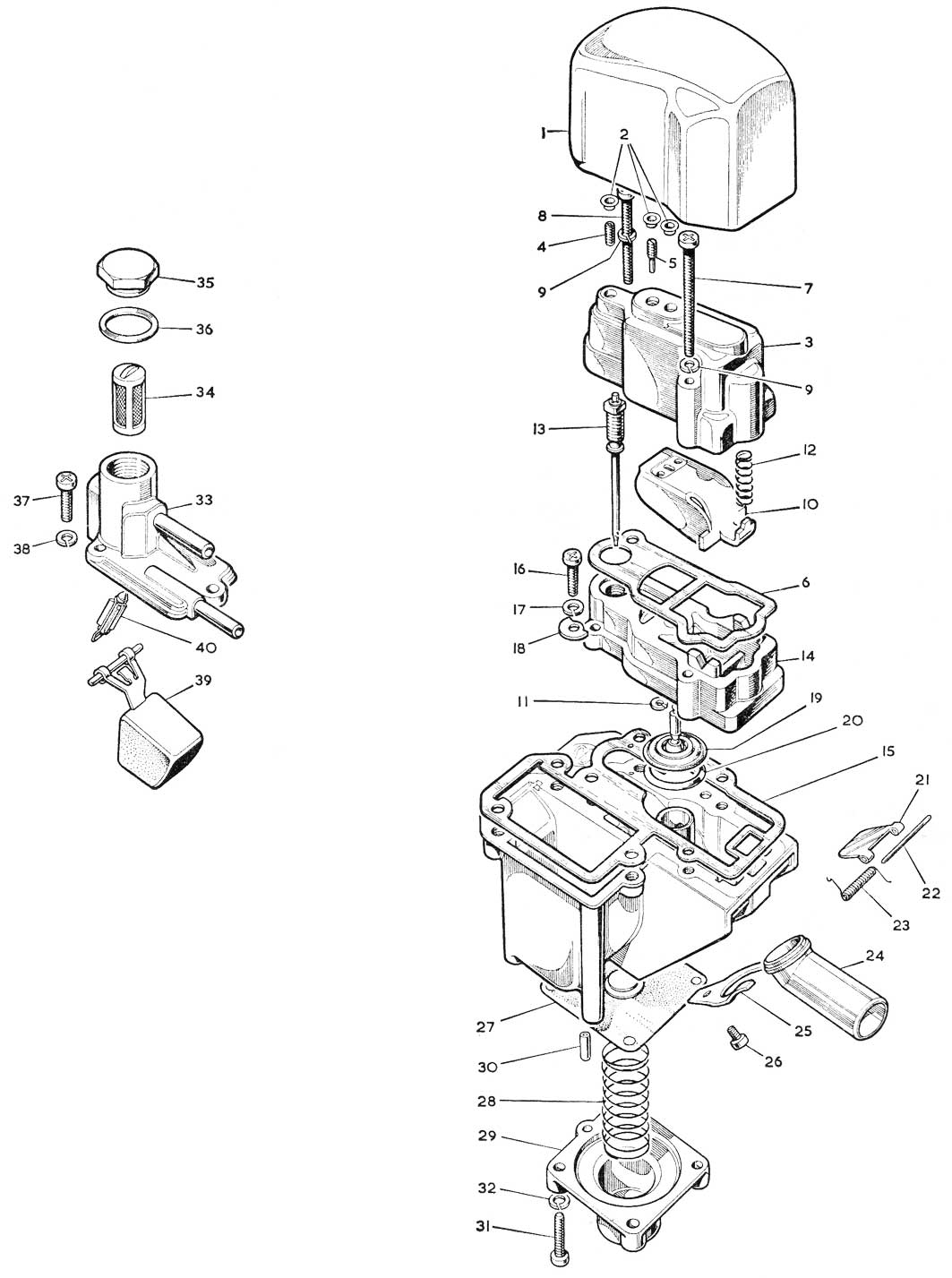
Diagram Number References
1 Cover - Heat Insulation
2 Plugs - Aluminium Blanking
3 Top Cover complete
4 Hollow Grub Screw - Adjusting Needle
5 Grub Screw - Adjusting Valve
6 Gasket - Top Cover
7 Screw- Long - Fixing Top Cover
8 Screw - Short - Fixing Top Cover
9 Spring Washer - Fixing Top Cover
10 Main Bi-Metal complete
11 Washer - Locating - Main Bi-Metal
12 Loading Spring - Main Bi-Metal
13 Jet Needle complete
14 Valve Body
15 Gasket - Float Chamber Lid and Valve Body
16 Screw - Fixing Valve Body
17 Spring Washer - Fixing Valve Body
18 Special Plain Washer - Fixing Valve Body
19 Main Valve and Diaphragm complete
20 Clamp Ring - Diaphragm
21 Flap - Air Entry
22 Spindle - Flap
23 Spring - Return for Flap
24 Elbow - Air Entry
25 Clamp - Retaining for Air Entry
26 Screw - Fixing Air Entry Pipe Clamp
27 Needle Diaphragm
28 Spring - Diaphragm
29 Cap - Needle Diaphragm
30 Hollow locating dowel - Cap and Needle Diaphragm
31 Screw - Fixing Diaphragm Cap
32 Spring Washer - Fixing Diaphragm Cap
33 Lid - Float Chamber
34 Nylon Filter
35 Plug - Filter
36 Washer - Filter Plug
37 Screw - Fixing Float Chamber Lid
38 Spring Washer - Fixing Float Chamber Lid
39 Float Complete
40 Float Needle
Dismantling
Important:
For unit removal and fitting information refer to the vehicle manufacturer’s instructions. The automatic enrichment device is a precision instrument and should be treated as such. This applies particularly to the bi-metal assemblies, which must not be distorted or bent in any way.
High standard of cleanliness are required when working on the automatic enrichment device. Petrol or paraffin may be used to clean the components. Use nylon cloth, never material that is fluffy or that leaves lint, when drying any components.
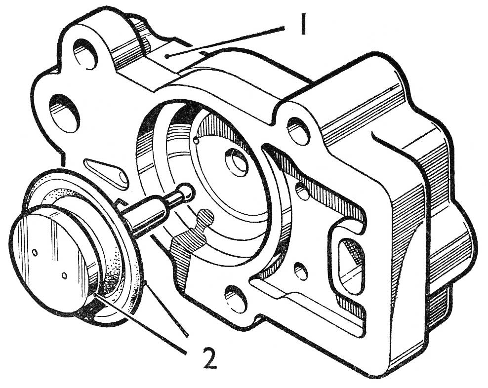
1. Remove the polypropylene heat insulation cover from the unit, and then use a penknife or thin-bladed screwdriver to prise out the three aluminium blanking plugs in the top cover.
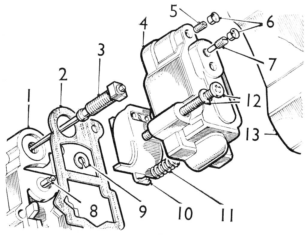
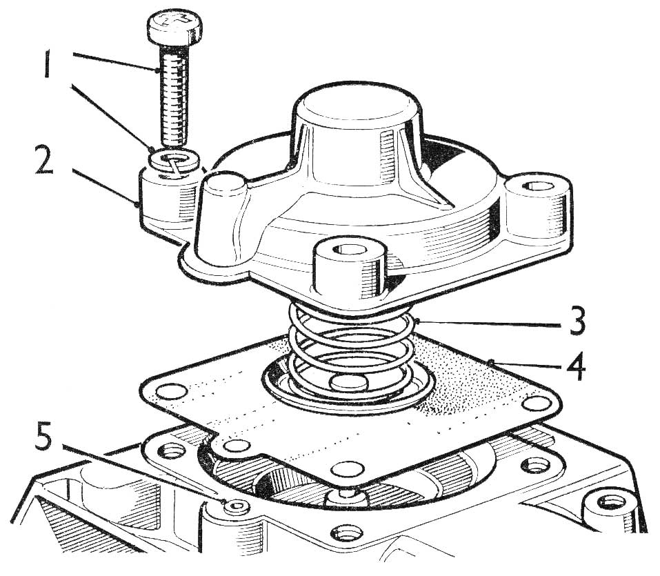
2. Hold the unit upright, taking great care to avoid damage. Unscrew the two long screws retaining the moulded Bakelite top cover and remove the cover carefully, separating it from the gasket if necessary. Remove the adjustment grub screws if replacement is necessary.
3. Carefully lift the main bi-metal complete out of the ‘V’ slots and disengage it from the top of the valve stem by sliding back over the ‘V’ slots. Remove the locating washer from the top of the valve stem. Unscrew the jet needle complete and withdraw it from the body. Remove the top cover gasket.
4. Unscrew the two screws retaining the moulded Bakelite valve body and remove the body. If the body is stuck to the lower body gasket, separate by tapping the side of the valve body with the handle of a screwdriver.
 |
 |
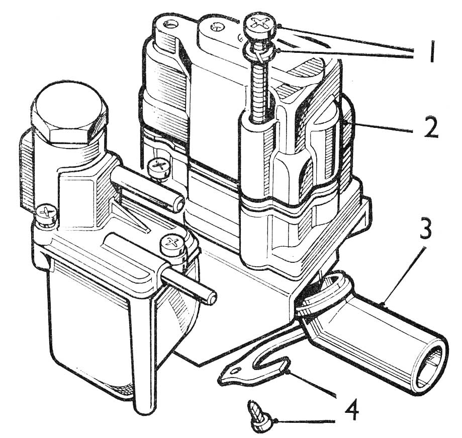
| 1. Valve Body 2. Gasket for top cover 3. Jet Needle complete 4. Top Cover 5. Hollow Grub Screw 6. Aluminium Blanking Screws 7. Grub Screw 8. Valve Stem 9. Locating Washer 10. Main Bi-Metal complete 11. Loading spring for main Bi-Metal complete 12. Screw and Washer fixing top cover 13. Heat Insulation Cover |
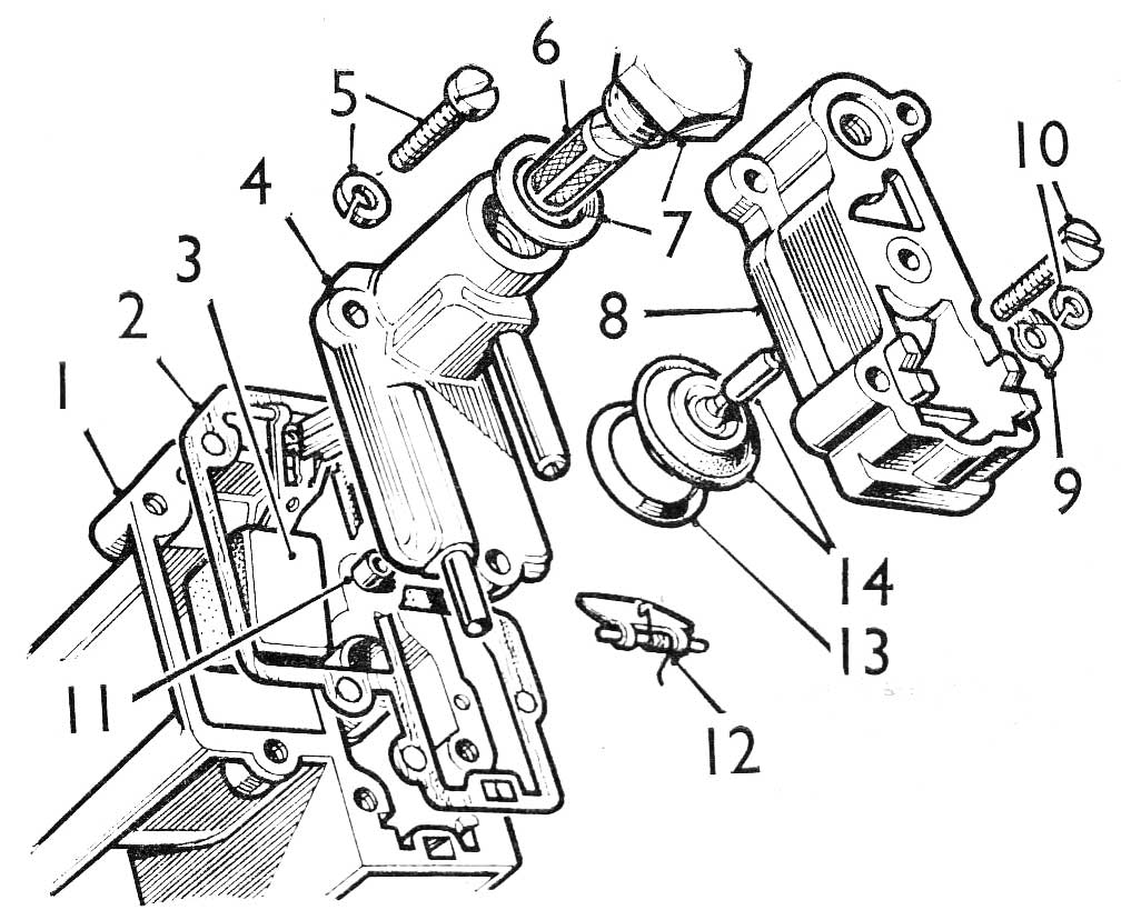
1. Main Body 2. Gasket for valve body 3. Float 4. Float Chamber Lid 5. Screw and Nylon fixing bolt 6. Nylon Filter 7. Plug and Washer retaining nylon filter 8. Valve Body 9. Special Plain Washer fixing valve body 10, Screw and Spring Washer fixing valve body 11. Jet Tube 12. Air Entry valve, spindle and spring 13. Clamp Ring for Diaphragm 14. Main Valve and Diaphragm |
5. Depress the main valve, and then ease the pressed steel diaphragm clamp ring out of the valve body taking care not to damage the moulded rubber diaphragm surrounding the main valve head. Remove the main valve assembly, complete with the diaphragm, from the valve body. Lift the lower body gasket in order to remove the air entry flap valve, together with the spindle and spring.
6. Unscrew the large screw plug and remove the filter.
7. Unscrew the three screws retaining the float-chamber lid and remove the lid carefully. If it is stuck to the main body, separate by tapping the side of the lid with the handle of a screwdriver. Remove the float needle and float assembly complete with the hinge pin. The float needle may now be detached from the float by unhooking the wire stirrup. Re-move the lower body gasket.
8. Take the main body and noting that the brass jet tube protrudes above the face of the casting, place the body upside down on a piece of wood having a hole drilled to accommodate the protruding jet tube. It is important that no load is applied to the top of the jet tube any time; otherwise the jet location may be altered.
9. Unscrew the four screws retaining the needle diaphragm cap and hold the cap against the load of the spring inside it whilst withdrawing the screws. If the cap is stuck to the diaphragm, hold the unit firmly, then separate by tapping smartly at the side with the handle of a screwdriver. Remove the cap, spring, diaphragm, and hollow locating dowel from the main body.
10. Unscrew the screw retaining the air entry pipe clamp and remove the air entry pipe and clamp.
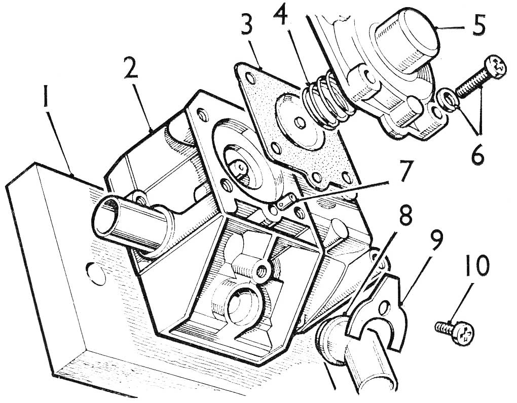
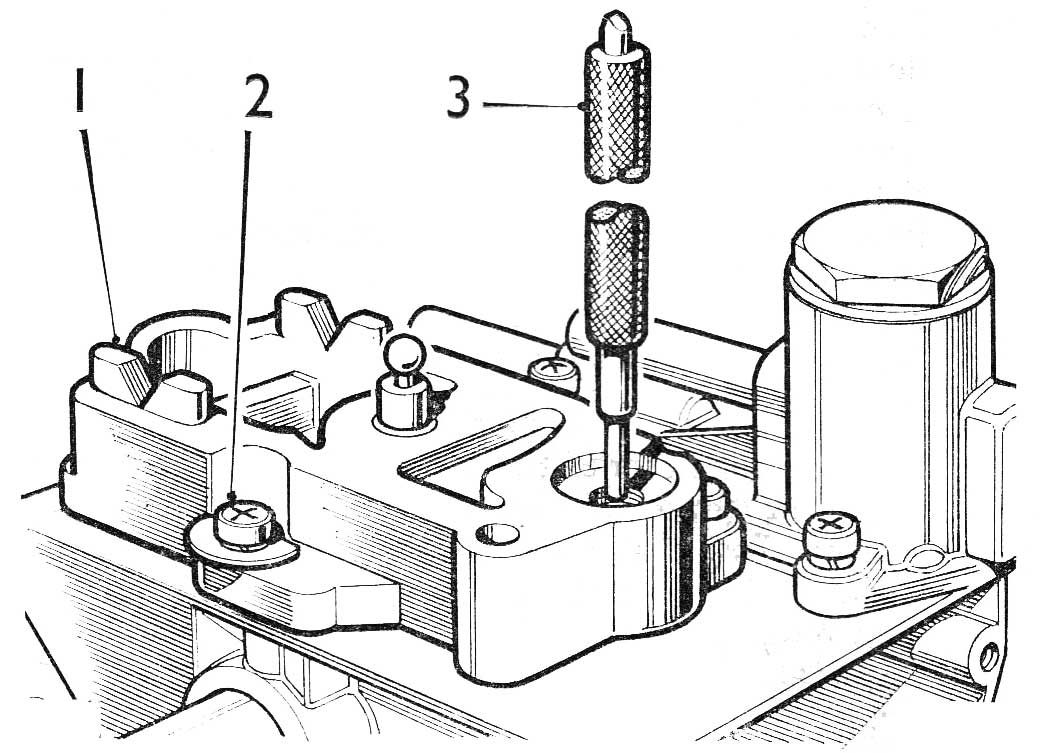
1. Wooden block with a drilled hole to accommodate the Brass Jet Tube
2. Body Casting
3. Diaphragm
4. Spring for Diaphragm
5. Diaphragm Cap
6. Screw and Washer fixing Diaphragm Cap
7. Hollow Locating Tunnel
8. Air Entry Pipe
9. Clamp Retaining Air Entry Pipe
10. Screw Fixing Clamp
Inspection
11.
Wash all components, using clean petrol or paraffin only. Then examine all parts carefully for damage.
Ensure that all drilled holes in the main body are free from obstructions.
Examine the valve body and ensure that all holes are clear.
Check that the valve stem articulates freely in the valve head and that the two air bleed holes in the head are clear.
Check that the rubber diaphragm has not been damaged.
Examine the needle assembly and check for free movement in the adjuster screw and straightness of shaft.
Check that the bi-metal assembly in the top cover moves freely on its mounting screw. Do not remove bi-metal from cover.
Check that all pipes and drillings in the float-chamber lid are clear and that the filter is clean.
Examine the float needle tip for wear or damage, also the seating in the float-chamber lid.
Ensure that the float assembly pivots freely in the float-chamber with clearance all round and that there is side-play on the float spindle in the body recesses.
Reassembling
1. Place the main body upside down on a piece of wood with a hole for the protruding jet tube.
 |
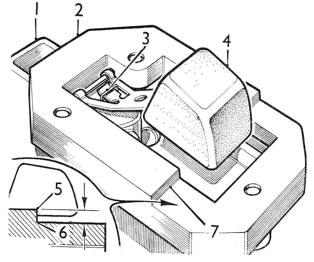 |
| 1. Screw and Washer Fixing Diaphragm Cap 2. Cap for Diaphragm 3. Spring for Diaphragm 4. Diaphragm 5. Hollow Dowel Locating Diaphragm and Cap |
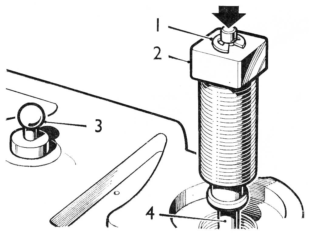
1. Float Chamber Lid 2. Checking Tool 3. Stirrup for Needle 4. Float 5. Upper Setting Limit 6. Lower Setting Limit 7. Setting Limit Indication |
2. Ensure that the hollow dowel is free from obstruction, and then fit it to the main body. Place the diaphragm over the dowel, with the flat rivet head downwards and align it with the screw holes. Position the spring in the locating plat of the diaphragm. Place the cap over the spring and press down taking care to engage with the hollow dowel and to keep the screw holes aligned. Whilst holding the cap down against the pressure of the springs check that the diaphragm has not puckered around the edges of screw holes. Fit four screws with spring washers and tighten evenly.
3. Check the float level as follows;
1. Invert the float-chamber lid.
- Locate the float needle and float to the lid, using checking tool for float lid, part no 606000, as illustrated.
- Check that the float level as illustrated; the float should rest lightly on the needle.
- If the float is outside the limits, adjust by setting tongue on the float lever.
- Remove the special tool together with the float and float needle.
4. Hold unit correct way up.
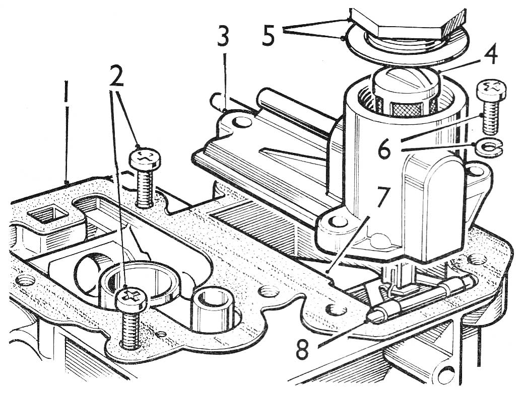
5. Position the lower body gasket on the top face of the body and locate it with two screws opposite to the float-chamber.
 |
 |
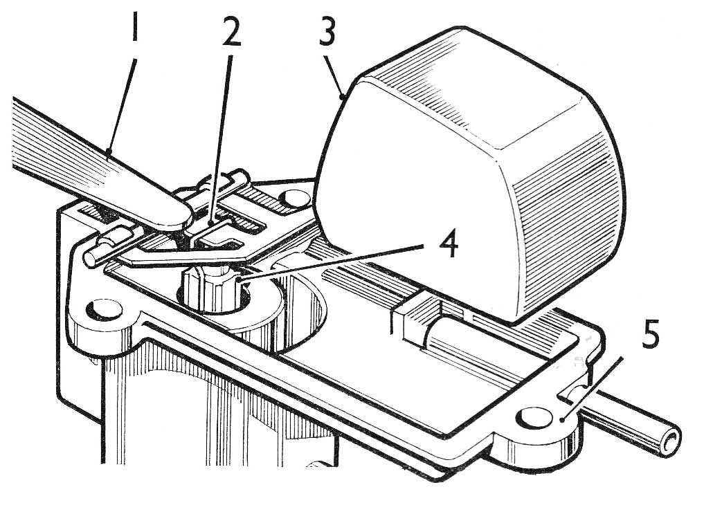
| 1. Float held against the face of the lid with a steel rule 2. Stirrup or Float Needle 3. Float 4. Float Needle 5. Float Chamber Lid |
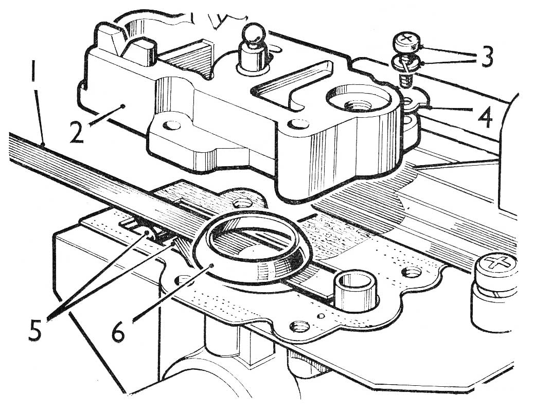
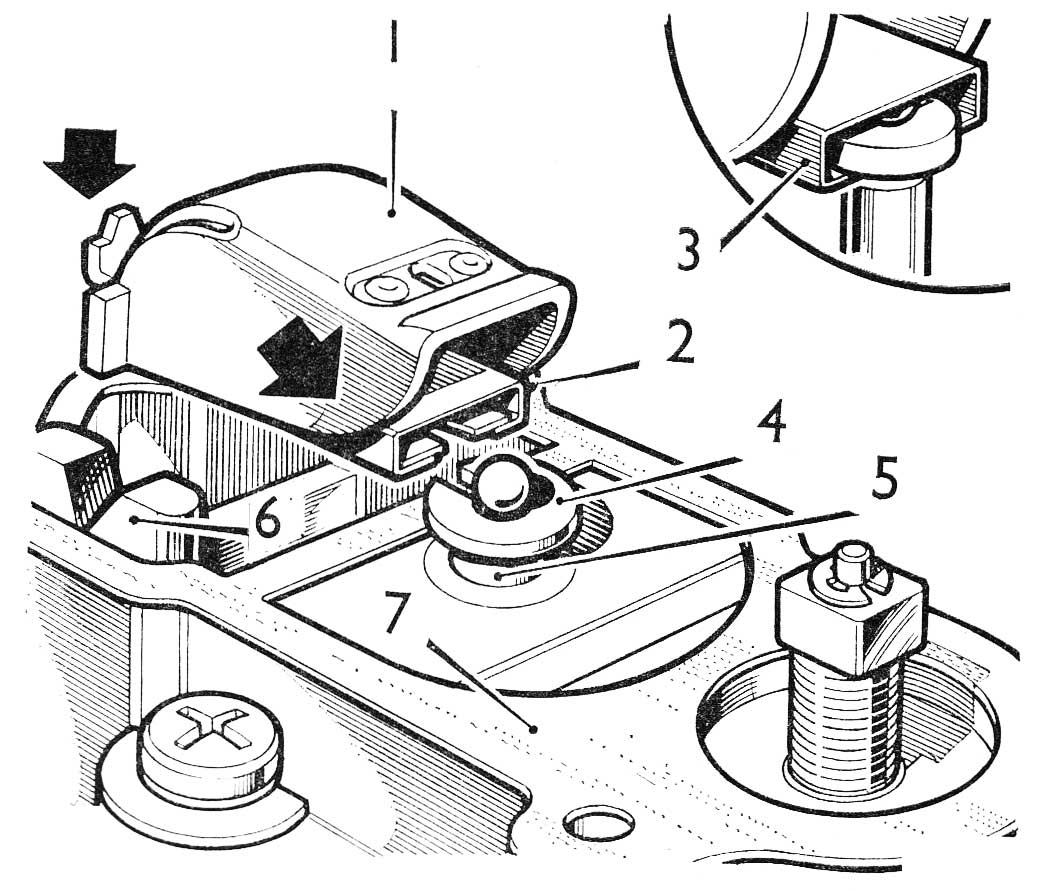
1. Gasket 2. Locating Screws for Gaskets 3. Float Chamber Lid 4. Nylon Filter 5. Plug and Washer Retaining Nylon filter 6. Screw and Washer fixing Float Chamber Lid 7. Float 8. Ensure hinge pin falls into the recesses of body |
6. Drop the needle into the seating of the inverted float-chamber lid. Then ensure that the float needle is correctly located on the float lever by the wire stirrup. Holding the float assembly to the face of the lid with the tip of a steel rule or feeler gauge. Position the lid over the float-chamber close enough to allow the float assembly to be dropped, so that the hinge pin falls into the recesses in the body without disengaging the needle from the seating bore.
Lower the lid onto the main body, align the screw holes, fit three screws and spring washers, and tighten. Test that the float is moving freely in the chamber by rotating the whole unit around the float hinge pin axis and listen for the movement of the float. Remove the two screws used to locate the gasket.
7. Replace the filter in the float-chamber lid using a new aluminium washer; refit the plug and tighten.
8. Fit the main valve assembly to the valve body and ensure that the stem moves freely in the bush.
 |
 |
| 1. Valve Body 2. Main Valve and Diaphragm |
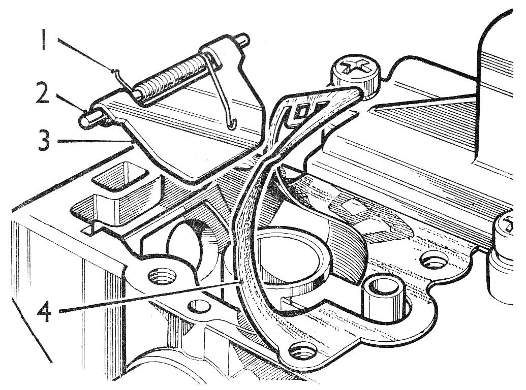
1. Spring in the loaded position 2. Spindle 3. Air Entry Flap Valve 4. Gasket turned back to allow the valve to be fitted |
9. Assemble the air entry flap valve with the spring and spindle. Turn back the gasket to allow the air entry valve to be fitted with the spring in the loaded position. Replace the gasket and ensure that its edges do not foul the air entry valve.
 |
 |
| 1. Steel rule in the position over main body 2. Valve Body 3. Screw and Washer fixing valve body 4. Special plain washer fixing valve body 5. Air Entry Flap Valve 6. Diaphragm Clamp Ring |
1. Valve Body 2. Screw and Washer fixing valve body 3. Allignment bar for valve body and jet tube |
Place a steel rule along the main body to cover the valve seating and hold the air entry valve in place. Position the diaphragm clamp ring directly over the main valve seat on the steel rule. Pick up the valve body by the top of the valve stem and position it carefully over the main body so that the clamp ring engages in the diaphragm recess.
Align the screw holes, fit two short screws with spring washers and fixing tags and lightly tighten. Remove the steel rule. It is important that the threaded insert in the valve body is aligned with the jet tube bore. This should be done carefully by the use of an alignment bar. Part no. 9005. This is a metal bar having two diameters; the smaller, 185in (4.7 mm) dia. being not more than 75in (19 mm) long, and the larger, 218in (5.55 mm) dia, being not less than 1in (25 mm) long.
The small diameter end is fitted into the jet tube and the valve body adjusted so that the larger diameter can pass through the insert to abut against the top of the jet tube. The retaining screws can then be tightened and the alignment bar withdrawn. Check that the air entry valve operates freely, by carefully lifting the valve against the spring with a pencil through the air entry hole.
 |
 |
| 1. Air Entry Flap 2. Pencil |
1. Circlip 2. Adjuster screw for Jet Needle 3. Valve Stem 4. Jet Needle |
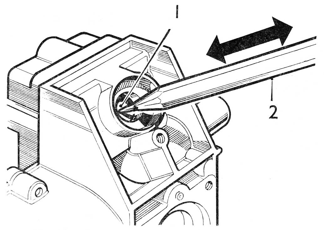
10. Drop the jet needle complete into the jet tube and screw the square-headed adjuster screw into the valve body about three complete turns. An approximately correct mixture setting can be obtained by the following method;
Press the top of the jet needle down. As arrowed so that the top circlip is firmly against the top of the adjusting screw and proceed to screw the adjuster down. As soon as the jet needle can be felt to have seated in the jet (recognized when the adjuster leaves the circlip behind) screw the adjuster up until it can be seen to have abutted against the circlip. Release the pressure off the top of the jet needle. Now note the position of the needle adjuster and then turn it anti-clockwise three flats (3/4 turn)
11. Position the top cover gasket on the main body; Fit the locating washer to the ball top of the valve stem. Take bi-metal complete and engage the spring clip with the locating washer on the valve stem. Position the ears of the bi-metal heat shroud in the ‘v’ slots of the valve body.
12. It should be noted before fitting the top cover that there are serrations moulded into the top cover to hold the needle adjusting screw in position. These serrations allow 12 positions of the adjuster in one complete turn. Before fitting the top cover therefore, the needle adjuster should be positioned to the nearest setting to line up with the serrations in the top cover cap.
 |
 |
| 1. Main Bi-Metal complete 2. Spring Clip 3. Valve Stem and locating washer correctly assembled 4. Locating washer on valve stem 5. Valve Stem 6. 'V' slots in valve body 7. Gasket on main body |
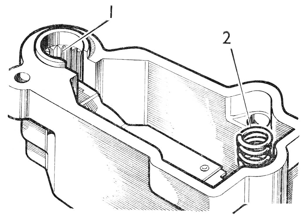
1. Serrations in the top cover 2. Loading Spring for the main bi-metal complete |
13. Ensure the main bi-metal loading spring is located in position in the top cover, and then place the top cover squarely in position over the valve body taking care not to disturb the jet needle setting. Press the cover down firmly against the load of the main bi-metal loading spring and hold it in position. Fit two long screws with spring washers, and tighten
14. Fit the air inlet pipe as illustrated, and then secure it with clamp and screws.
15. Adjust the main valve and jet needle lift.
16. Fit the new blanking plugs to the top cover.
1. Screw and Washer fixing top cover
2. Top cover
3. Air Inlet Pipe correctly positioned