Description
Purpose
The Auxiliary carburetter is used on certain installations to provide automatically different degrees of mixture enrichment at; Starting.
Idling and light cruising conditions
Full throttle conditions. It may be used with single or multi carburetter installations.
Control
The unit may be controlled by either;
A thermostatically operated switch housed in the cylinder head coolant jacket and set to bring the apparatus into operation below 35’C (95’F)
A manually operated switch, which is generally provided with a warning light.
Operation
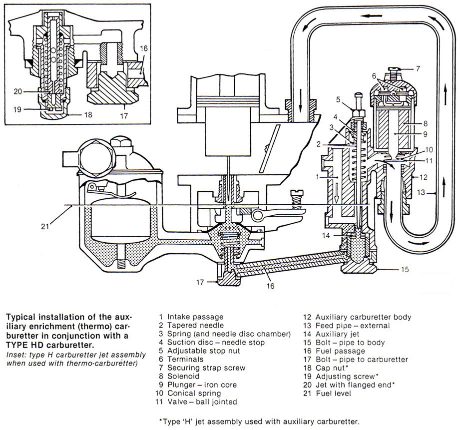
The auxiliary carburetter is a separate unit attached to the main carburetter. When fitted to ‘H’ type carburetters the construction of the main carburetter jet assembly differs from normal in the method of mixture adjustment.
The device consists of a solenoid operated valve and a fuel metering needle which draws its fuel from the base of the auxiliary jet supplied from the main carburetter.
When the device is operated, air is drawn from the atmosphere through the air intake into a chamber and is mixed with fuel as it passes the jet. The mixture then passes upwards pas the shank of the needle, through a passage, and so past the aperture provided between the valve and its seating. From here it passes directly to the main induction manifold through the external feed pipe as shown.
Solenoid and Valve
The device is brought into action by energizing the solenoid. The iron core is thus raised carrying with it the ball-jointed disc valve against the load of the conical spring, thereby opening the aperture between valve and seating.
Valve Seating
A cup washer is fitted against the solenoid face to centralize the conical spring. Any leakage between the valve and its seating would allow the device to operate and affect the idling setting of the main carburetter(s).
If the solenoid is energized while the engine is idling the valve will not normally lift owing to the high manifold depression; the act of opening the throttle will reduce manifold depression and allow the device to operate.
Fuel Level
The fuel level in the auxiliary carburetter is controlled by the main carburetter float-chamber. It can be seen from the illustration that this results in a reservoir of fuel remaining in the well of the auxiliary carburetter.
Fuel Well
When starting with the device in operation, this fuel is drawn into the induction manifold to provide the rich mixture necessary for instant cold starting.
Needle and disc
When the valve has lifted, the needle disc chamber is in direct communication with the inlet manifold and the depression, dependent on throttle opening, varies the position of the needle by exerting a downward force upon the suction disc and needle assembly, thus;
At idling the relatively high depression will draw the needle into the jet until the needle head abuts against the
At larger throttle openings a reduced depression is communicated to the needle disc chamber and the spring will tend to overcome the downward movement, of the needle, that increasing mixture strength. adjustable stop.
Tuning and Adjustment
Main Carburetter(s)
As both the main and the auxiliary carburetters operate when starting from cold, the main carburetter(s) must be tuned correctly before attempting any adjustment to the auxiliary carburetter. Reference should be made to the appropriate Service Sheets and to the mixture adjustment instructions given below for ‘H’-type carburetters.
Mixture adjustment – ‘H’ type carburetter
The procedure for mixture adjustment is the same as for normal ‘H’ type carburetter except that a jet adjusting screw is used in place of the normal jet adjusting nut (see inset opposite) as follows;
Remove the cap nut.
Adjust the jet as required, by turning the slotted screw up to weaken or down to enrich the mixture. The slight leakage of fuel through the jet during this operation can be ignored.
Replace the cap nut with its sealing washer.
Auxiliary Carburetter
Tuning of the Auxiliary carburetter is confined to adjustment of the stop nut which limits the downward movement of the needle, and is carried out with the engine running at normal temperature and the main carburetters) tuned.
Procedure as follows;
Switch on the auxiliary carburetter.
Where the thermostat has automatically broken the circuit, energize the solenoid by short-circuiting the thermostatic switch to earth, or if this is inaccessible, earth the appropriate terminal of the auxiliary carburetter with a separate wire.
Where a manual switch is fitted, switch on.
Open the throttle momentarily to allow the valve to lift.
Adjust the stop nut (see diagram below)
Initially clockwise (to weaken) until the engine begins to run erratically.
Then anti-clock-wise (to enrich) through the phase where the engine speed has risen markedly to the point where over-richness results in the engine speed dropping to between 800-1,000 r.p.m with the exhaust gases noticeably black in colour.