Electric Fuel Pump: Dismantling
For location of all components, refer to the explosion diagrams found in the Single Type Electric Fuel Pumps Section.
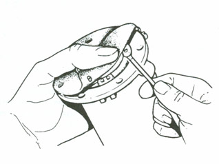
Contact Breaker
(a) Remove the insulating sleeve, terminal nut and connector, together with its shakeproof washer. Remove the tape seal (if fitted) and take off the end cover. (b) Unscrew the 5 BA screw which holds the contact blade to the pedestal. This will allow the washer, the long coil lead and the contact blade to be removed.
Coil Housing and Diaphragm
(a) Unscrew the coil housing securing screws using a screwdriver with a well-fitting blade to avoid damaging the screw heads. (b) Remove the earthing screw. (c) The coil housing may now be removed from the body. Next turn back the edge of the diaphragm assembly and remove the armature guide plate from the coil recess by gently probing the two end lobes free from the coil recess. (Later versions use five figure of eight shaped centring plates instead). (d) Now remove the diaphragm and spindle assembly by taking hold of the diaphragm and unscrewing it anti-clockwise until the armature spring pushes the diaphragm away from the coil housing.
Pedestal and Rocker
(a) Remove the end-cover seal washer, unscrew the terminal nut and remove the lead washer; this will have flattened on the terminal tag and thread and is best cut away with cutting pliers or a knife. (b) Unscrew the 2 BA screws, holding the pedestal to the coil housing and remove the earth terminal tag. (c) Tip the pedestal and withdraw the terminal stud from the terminal tag. The pedestal may now be removed with the rocker mechanism attached. (d) Push out the hardened steel pin which holds the rocker mechanism to the pedestal and separate the two parts. (e) Dual Type: Repeat these operations on the other pump unit.
Body and Valves
(a) L and HP Types: Remove the inlet union, then the outlet union, the outlet valve cage and the inlet valve disc. Remove the base plug and filter. (b) AUF 200/AZX 1200: Unscrew the 2 BA screws securing the spring clamp plate which holds the inlet and outlet nozzles. Remove the nozzles, filter and valve assemblies. (c) AUF 300/AZX 1300: Undo the two screws securing the valve clamp plate, remove the valve caps, valves, sealing washers and the filter. (d) Dual Type: Unscrew the four Philips screws securing the valve clamp plates, remove the valve caps, valves, sealing washers and filter.
Note: Dismantling of the delivery flow smoothing device should only be undertaken if the operation of it is faulty, and if the necessary equipment for pressure-testing after assembly is available. On this understanding proceed as follows:
(e) Remove the four 4 BA screws securing the delivery flow smoothing device cover. (f) Remove the cover, rubber O ring, barrier and sealing washer. (g) Remove the single 2 BA screw securing the inlet air bottle cover. Remove the cover and gasket, then unscrew and inlet and outlet connections.