HD Type Carburetter: Dismantling
1
(a) Thoroughly clean the outside of the carburetter.
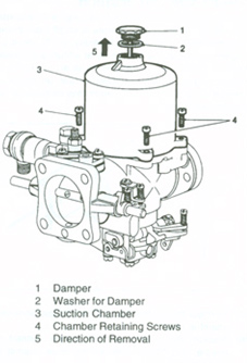
(b) Unscrew and remove the damper and washer.
(c) Remove the suction chamber retaining screws and remove the chamber without tilting it.
2
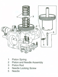
(a) Lift off the piston spring.
(b) Carefully lift out the piston and needle assembly, and empty the damper oil from the piston rod.
(c) Remove the needle locking screw and withdraw the needle. If it cannot be removed easily, tap the needle inwards first and then pull outwards. Do not bend the needle.
3
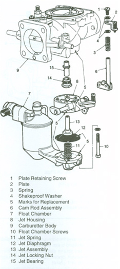
(a) Remove the plate retaining screw and lift off the plate and spring, noting the shake proof washer either sideof the plate. Withdraw the cam rod assembly.
(b) Mark the relative positions of the float chamber, jet housing and carburetter body. Unscrew the float chamber screws, holding the float-chamber against the pressure of the jet spring, then detach the float chamber carefully.
(c) Lift out the jet spring. Mark the jet diaphragm opposite one of the screw holes in the jet housing and withdraw the jet assembly, then lift off the jet housing.
(d) Using a ring spanner, slacken and remove the jet locking nut together with the jet bearing.
4
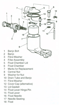
(a) Unscrew the banjo bolt and remove the bolt, banjo, and fibre washers. Extract the filter and spring assembly from inside the float-chamber lid inlet.
(b) Mark the relative positions of the float chamber and lid. Remove the central nut retaining the float-chamber lid together with the drain-tube banjo and fibre washer, or cover cap, if fitted.
(c) Detach the lid and gasket. Push out the float lever hinge pin from the end opposite to the serrations, then detach the lever.
(d) Extract the float needle from its seating and unscrew the seating from the lid using a box spanner 8.58 mm 0.338 in) across the flats. Do not distort the seating.
(e) Invert the chamber to remove the float.
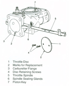
5
(a) Close the throttle and mark the relative positions of the throttle disc and the carburetter flange.
(b) Slacken and remove the disc retaining screws.
(c) Withdraw the disc from its slot in the throttle spindle.
(d) The disc is oval and will jam if care is not taken.
(e) Slide out the spindle from its bearings.
(f) The throttle spindle sealing glands should not be removed as they require no servicing.
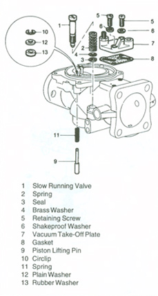
6
(a) Unscrew and remove the Slow-running valve complete with spring, seal and brass washer.
(b) Remove the two screws and shake proof washers retaining the vacuum ignition takeoff plate and union. Lift off the plate and gasket.
(c) Remove the piston lifting pin by extracting the circlip from its groove with the pin pressed upwards, and then withdraw the pin downwards.