HD Type Carburetter: Reassembly
Throttle Spindle Bush Replacement
Throttle spindle bush replacement should be undertaken as follows. Note: some HD8 carburetters are fitted with plastic spindle bushes which are now no longer available.
1. Dismantle the carburetter as described. Remove P.T.F.E. bushes from carburetter body where fitted.
2. Line ream throttle spindle bores from both sides using a 9.5 mm diameter reamer (see note below). Finished bore size should be 9.5 mm in diameter.
3. Using a service tool shown (part no. ABF 185) drive replacement bushes into the body.
4. Remove all swarf and burr from the body.
5. Reassemble throttle spindle and disc assembly fitting spindle seals supplied in the service kit. Position the seals* so that the sealing face is in contact with the carburetter body.
Note: Care must be taken not to exceed length of the bush when machining so as to not break through into the carburetter venturi. The bushes can then be pushed into place until flush with the body. If break through does occur it will be necessary for the bush to be pushed through to protrude into the venturi and then milled down flush to match the shape of the venturi wall. This will ensure the throttle disc is able to give a good seal in the area close to the spindle.
Before reassembling, examine all the components for damage and/or wear. Unserviceable components must be renewed.
1
(a) Examine the throttle spindle for scoring or signs of wear. Refit the spindle in its bearings and check for slack in the bearings and for freedom of operation. (b) Refit the throttle disc in the slot of the throttle spindle in the position as marked when dismantling. The countersunk ends of the screw holes in the spindle must face outwards towards the flange of the carburetter body. Insert two new retaining screws but do not tighten. (c) Adjust the disc until it closes fully. Check this visually, and then tighten the screws. Spread the split ends of the screws just enough to prevent them from turning
2
(a) Examine the slow-running valve seal for serviceability. Check that the concave face of the brass washer is towards the seal. Refit the valve assembly. (b) Check that the passages in the carburetter body and the vacuum ignition take-off plate are not obstructed. Examine the gasket for re-use and refit the gasket, plate, and securing screws. Tighten securely. (c) Refit the piston lifting pin, spring, rubber washer, plain washer and circlip.
3
(a) Examine the float needle and seating for damage or wear. Screw the seating into the float-chamber lid but do not over tighten. Refit the needle to the seating, coned-end first. Test the assembly for leakage with airpressure. (b) Refit the float lever and insert the hinge pin. Check the float level as described on page 21. (c) Examine the float for damage or punctures. Refit the float to the float-chamber. (d) Examine the lid gasket for re-use. Fit the gasket to the lid and then replace the lid on the chamber as marked on dismantling. Fit the fibre washer, drain tube banjo, plain washer, and nut or cover cap and nut, as applicable. Do not over tighten the nut. (e) Clean the filter assembly and examine for damage. Refit the filter to the lid inlet, spring end first. Refit the banjo, fibre washers and banjo bolt. The recessed face of the banjo must be towards the hexagon of the bolt.
4
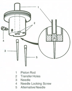
(a) Examine the piston assembly for damage to the piston rod and the outside surface of the piston. The piston assembly must be scrupulously clean. Use either petrol or mentholated spirits as a cleaning agent. Do not use abrasives. Lightly oil the outside of the piston rod. (b) Clean inside the suction chamber and piston rod guide using petrol or mentholated spirits. Refit the damper assembly and washer. Seal the transfer holes in the piston assembly with rubber plugs or Plasticine and fit the assembly to the suction chamber. Invert the complete assembly and allow the suction chamber to fall away from the piston. This operation should take between 5 and 7 seconds. If the time taken is in excess of that quoted the cause will be thick oil on the piston rod or an oil film on the piston or inside the suction chamber. Remove the oil from the points indicated and re-check.
5
(a) Refit the jet bearing and jet locking nut. Leave the nut sufficiently slack to allow the bearing to be moved from side to side. (b) Fit the jet assembly to the bearing in the same position as marked on dismantling. Centralize the jet as described on Routine Servicing. (c) Remove the jet and refit the jet housing, jet, jet spring and float-chamber in the same relative positions as marked on dismantling. Fit and tighten the securing screws evenly. (d) Replace the cam rod assembly and refit the spring, plate and plate retaining screw with a shake proof washer either side of the plate. Ensure the plate is positioned so that its adjustment screw strikes squarely on the lug of the throttle spindle operating arm.