HS2, HS4 and HS6 Carburetter: Dismantling
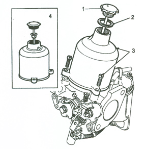
1
(a) Thoroughly clean the outside of the carburetters.
(b) Standard suction chambers. Remove the piston damper (1) and its washer (2), if fitted.
(c) Unscrew the suction chamber retaining screws (3).
(d) Lift the chamber assembly (4) vertically from the body without tilting it.
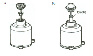
2
Ball bearing suction chambers (early type). Hold the piston firmly and pull the suction chamber, taking care not to bend the damper rod, until the bearing retainer is freed from the piston rod (5a). Remove the damper. Ball bearing suction chambers (later type). Remove the piston damper. Lift the piston and remove the bearing retaining circlip (5b).
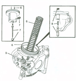
3
(a) Separate the suction chamber, the spring and the piston assembly and empty the oil from the piston rod (6).
(b) Unscrew the needle guide locking screw, then withdraw the needle, guide and spring (7). For fixed needle HS carburetters, refer to H Type Carbs: Routine Servicing for needle fitment and jet centring.
(c) Remove the piston lifting pin circlip and spring and withdraw the pin from the body (8).
(d) Release the pick-up lever return spring from its retaining lug (9).
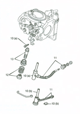
4
(a) Standard jet. Support the plastic moulded base of the jet and remove the screw retaining the jet pick-up lever and link bracket (when fitted)(10a). Capstat jet. Remove the clip holding the wire link to the jet housing (10b).
(b) Unscrew the jettube sleeve nutfrom the float-chamber and withdraw the jet assembly (11). Note the gland, washer and ferrule at the end of the jet tube.
(c) Remove the jet adjusting nut and spring (12).
(d) Unscrew the jet locking nut and detach the nut and jet bearing, withdraw the bearing from the nut (13).
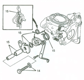
5
(a) Unscrew and remove the lever pivot bolt and distance washer (14).
(b) Detach the cam lever assembly and return springs, noting the pivot bolt tubes, skid washer and the locations of the cam and pick-up lever springs (15).
6
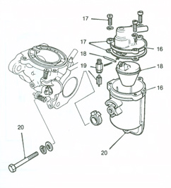
(a) Mark the float-chamber lid location to facilitate accurate reassembly (16).
(b) Remove the lid securing screws and detach the lid with its joint washer and float (17).
(c) Hold the float hinge pin at its serrated end and withdraw the pin and float (18).
(d) Extract the float needle from its seating and unscrew the seating from the lid (19).
(e) Remove the float-chamber securing bolt and the chamber (20).
7
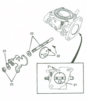
(a) Close the throttle and mark the position of the throttle disc in relation to the carburetter flange. Do not mark the disc in the vicinity of the overrun valve (21).
(b) Remove the throttle disc retaining screws, open the throttle and carefully withdraw the disc from the throttle spindle taking care not to damage the overrun valve (22).
(c) Tap back the tabs of the lock washer securing the spindle nut, remove the nut and detach the throttle lever, washer and the throttle spindle; note location of the lever in relation to the spindle and carburetter body (23).