


SU CARBURETTERS
TECHNICAL
HD Type Carburetter: Routine Servicing
Jet cantering
The piston should fall freely onto the carburetter bridge with a click when the lifting pin is released with the jet in the fully up position. If it will only do this with the jet lowered then the jet unit requires re-centring. This is done as follows:
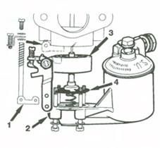
Step 1
- Mark the position of the jet housing and float-chamber in relation to the carburetter body for reassembly.
- Remove the plate retaining screw and withdraw the cam rod assembly (1).
- Unscrew and remove the float-chamber securing screws.
- Remove the float-chamber (2) and the jet housing (3) and then release the jet assembly (4).
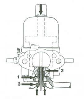
Step 2
- Slacken the jet locking nut (1), using a ring spanner, until the jet bearing (2) is just free to move.
- Remove the piston damper, hold the jet (3) in the 'fully up' position and apply light pressure to the top of the piston rod. Tighten the jet locking nut (1).
- Check again as in item 1 and ensure that the jet moves down the bearing freely.
- Reassemble, ensuring that the jet and diaphragm are kept to the same angular position and that the beaded edge of the diaphragm is located in the housing groove.
- Refill piston damper with oil (see tuning section).
Cleaning
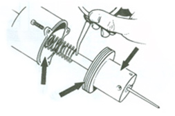
- Remove the piston/suction chamber unit.
- Using a petrol-moistened cloth, clean the inside bore of the suction chamber and the two diameters of the piston.
- Lightly oil piston rod only and reassemble
Float Chamber Fuel Level
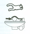
- Remove and invert the float-chamber lid.
- With the needle on its seating, insert a 11.0 mm (7/16 in) diameter bar between the forked lever and the lip of the float-chamber lid.
- The prongs of the lever should just rest on the bar. If they do not, carefully bend at the star of the pronged section until they do.
Needle Size and Position
The needle size is determined during engine development and will provide the correct mixture strength except under the extremes of temperature, humidity, or altitude; e.g. a weaker needle will be necessary at altitudes exceeding 1800 m (6,000 ft). If modifications are made to the engine; (e.g. camshaft, compression ratio, air cleaner, or exhaust system) a different needle may be necessary to maintain performance.
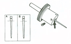
- To check the needle fitted, remove the piston/suction chamber unit.
- Slacken the needle clamping screw, extract the needle and check its identifying mark against the recommendation.
- Fit the correct needle and lock it in position so that the shoulder on the shank (A), or the lower edge of the groove (B), is flush with the piston base.
- Reassemble the piston/suction chamber unit.